Removal Procedure
Tools Required
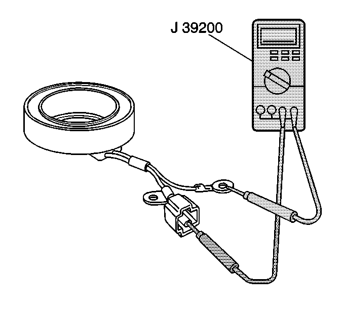
| • | J 39200 Digital Multimeter |
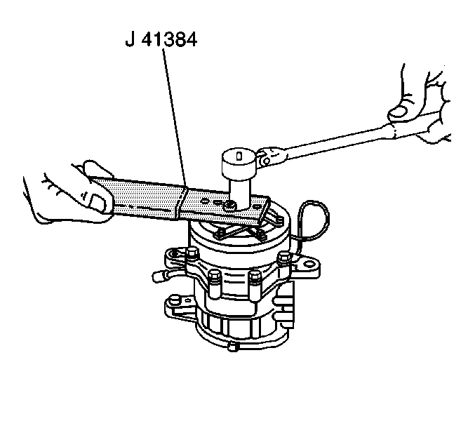
| • | J 41384 Clutch Plate Holder/Remover |
- Remove the compressor from the vehicle. Refer to Compressor Replacement .
- Remove the pressure plate nut and the washer from the drive shaft using the J 41384 .
- Remove the pressure plate from the drive shaft using the J 41384 .
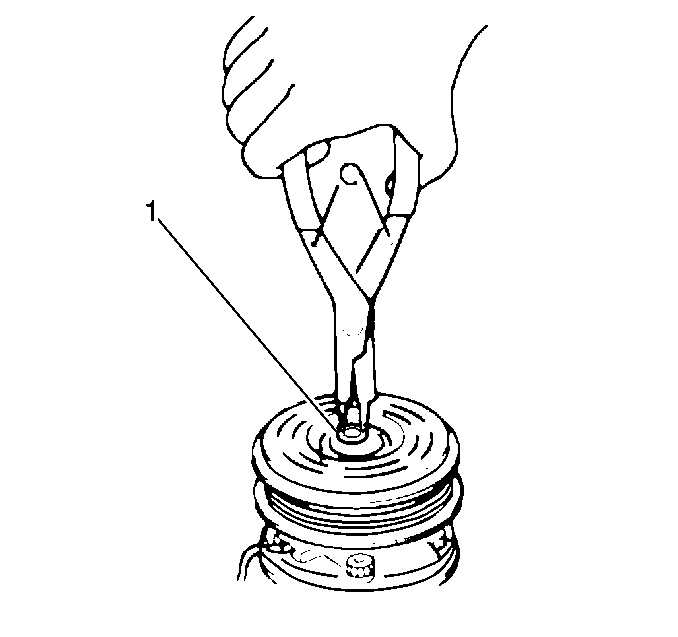
- Remove the clutch pulley snap ring (1) and the shim. Use the appropriate snap ring pliers.
- Remove the clutch pulley from the compressor by tapping with a plastic hammer.
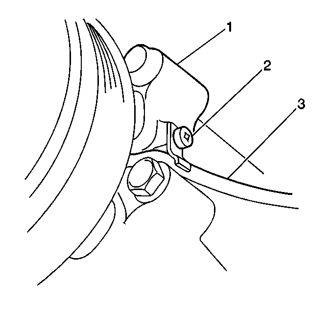
- Remove 1 screw (2) and the clutch coil wire retainer.
- Remove the clutch coil snap ring using the snap ring pliers.
- Remove the clutch coil from the compressor.
- Inspect the pressure plate for excessive wear and for scoring. Replace the pressure plate as necessary.
- Inspect the clutch pulley for excessive wear and for scoring. Replace the clutch pulley as necessary.
- Measure the clutch coil resistance using the J 39200 . Replace the clutch coil if the resistance is not within specifications.
Important:
• Discharge and recover the A/C system refrigerant, and remove the
compressor from the vehicle, before performing compressor repairs. • During service of the compressor, prevent dirt and other foreign
material from getting on the compressor parts and into the system. Clean
tools and a clean work area are essential for proper service. Keep the compressor
and the parts clean at all times. • Clean all of the parts that you will reassemble with a suitable
solvent, and air-dry the parts. • Use only lint-free cloths in order to wipe the parts. • Drain and discard the oil that remains in the compressor. Add
90 ml (3.0 fl oz) of new refrigerant oil when the repairs
are complete.
Important: During removal, do not damage the clutch pulley.
Clutch Coil Resistance
2.9-3.8 ohms at 20°C (68°F).
Installation Procedure
Tools Required
J 41384 Clutch Plate Holder/Remover
- Install the clutch coil to the compressor. Secure the clutch coil with the snap ring using snap ring pliers.
- Install the retainer of the clutch coil wire (3) to the compressor. Secure the retainer with the 1 screw (2).
- Install the clutch pulley to the compressor. Secure the clutch pulley with the snap ring (1) and with the shim.
- Install the pressure plate (1) to the compressor drive shaft.
- Adjust the clearance (2) between the clutch pulley (3) and the pressure plate. Replace the shim in order to obtain the proper clearance.
- Install the pressure plate washer and the nut to the compressor drive shaft using J 41384 .
- Install the compressor to the vehicle. Refer to Compressor Replacement .

Notice: Use the correct fastener in the correct location. Replacement fasteners must be the correct part number for that application. Fasteners requiring replacement or fasteners requiring the use of thread locking compound or sealant are identified in the service procedure. Do not use paints, lubricants, or corrosion inhibitors on fasteners or fastener joint surfaces unless specified. These coatings affect fastener torque and joint clamping force and may damage the fastener. Use the correct tightening sequence and specifications when installing fasteners in order to avoid damage to parts and systems.
Tighten
Tighten the screw to 2-2.5 N·m (17.1-22.12 lb in).

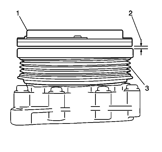
Pressure Plate-to-Pulley Clearance
0.35-0.65 mm (0.014-0.025 in).

Tighten
Tighten the pressure plate nut to 15-20 N·m (10.8-15.2 lb ft).
