Removal Procedure
- Discharge and recover the refrigerant. Refer to Refrigerant Recovery and Recharging .
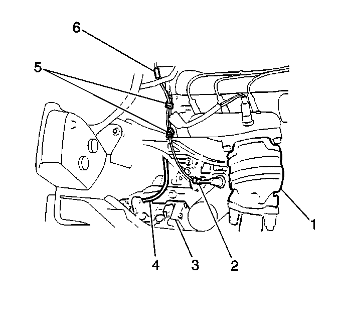
- Disconnect the compressor clutch electrical connector (6).
- Raise and suitably support the vehicle. Refer to Lifting and Jacking the Vehicle in General Information.
- Remove the engine splash shield. Refer to Engine Splash Shield Replacement in Body Front End.
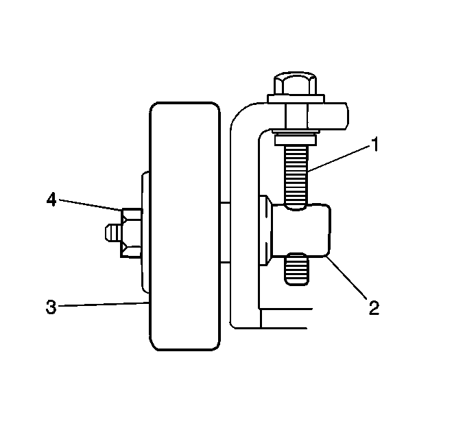
- Loosen the idler pulley lock nut (4).
- Loosen the idler pulley adjusting bolt (1).
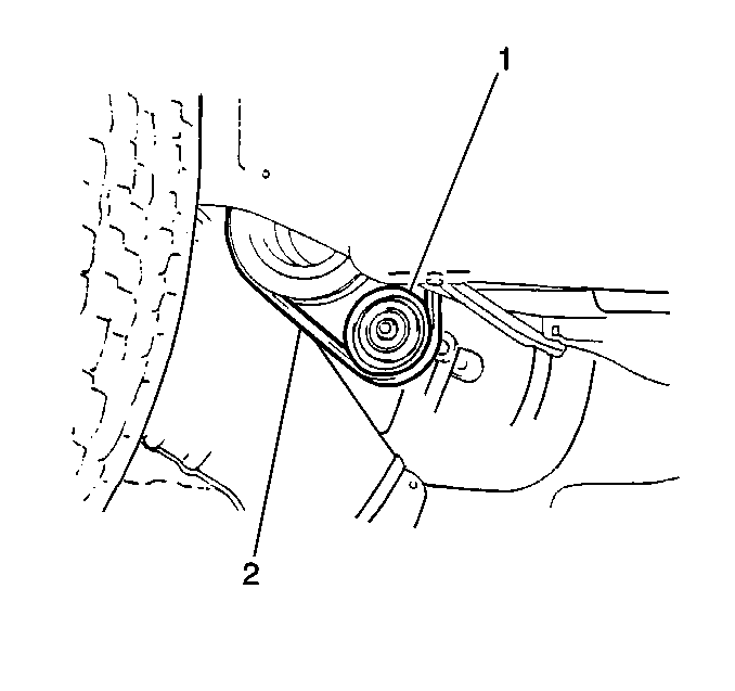
- Remove the compressor drive belt (2) from the clutch pulley.
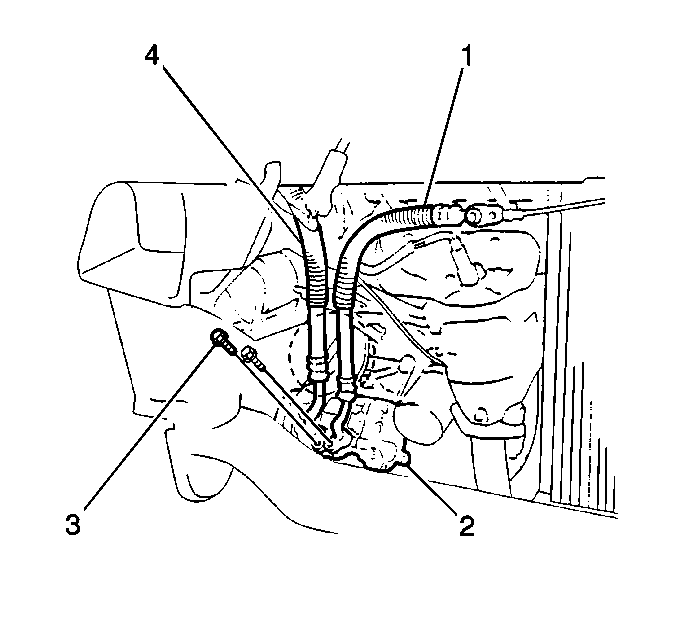
- Remove 1 bolt (3) and the discharge hose (1) from the compressor.
- Remove 1 bolt (3) and the suction hose (4) from the compressor.
- Discard the O-rings.
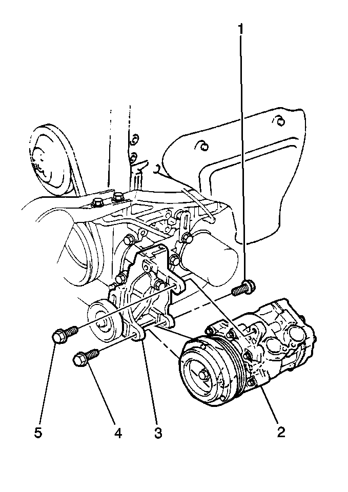
- Remove the 3 bolts (1,4,5) and the compressor from the vehicle.
- Cap all of the refrigerant line openings in order to keep dirt and moisture out of the system.
Installation Procedure
- Install the compressor to the compressor bracket. Secure the compressor with the 3 bolts. Tighten the bolts (1,4,5) in the following sequence:
- Tighten the bolts
- Install the compressor drive belt (2).
- Ensure that the belt is correctly aligned on the compressor pulley, on the crankshaft pulley, and on the power steering pulley, if equipped.
- Adjust the drive belt tension.
- Connect the compressor clutch electrical connector (6).
- Secure the electrical connector wire with the clamps (5).
- Coat the new discharge hose O-rings and the new suction hose O-rings with mineral base 525 viscosity refrigerant oil.
- Install the discharge hose and the suction hose (1,4) to the compressor.
- Install the engine splash shield. Refer to Engine Splash Shield Replacement in Body Front End.
- Lower the vehicle.
- Evacuate and recharge the air conditioning (A/C) system. Refer to Refrigerant Recovery and Recharging .
- Operate the A/C system, and inspect for refrigerant leaks. Refer to Leak Testing .
Important: When installing a new compressor, add 90 cc (3.0 fl oz) of refrigerant oil to the refrigeration system.

Important: Use the correct torque sequence in order to prevent damage to the compressor or to the compressor bracket.
| 1.1. | The front lower bolt (4) |
| 1.2. | The front upper bolt (5) |
| 1.3. | The rear bolt (1) |
Notice: Use the correct fastener in the correct location. Replacement fasteners must be the correct part number for that application. Fasteners requiring replacement or fasteners requiring the use of thread locking compound or sealant are identified in the service procedure. Do not use paints, lubricants, or corrosion inhibitors on fasteners or fastener joint surfaces unless specified. These coatings affect fastener torque and joint clamping force and may damage the fastener. Use the correct tightening sequence and specifications when installing fasteners in order to avoid damage to parts and systems.
Tighten
Tighten the compressor bolts to 22.5-27.4 N·m (16.5-20.1 lb ft).
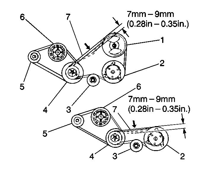

| 5.1. | Turn the idler pulley adjusting bolt (1) in order to obtain 7-9 mm (0.28-0.35 in) of belt deflection at 10 kg (22 lb) of force. |
| 5.2. | Tighten the idler pulley lock nut (4). |
Tighten
Tighten the idler pulley lock nut to 44.1-49 N·m
(32.4-36 lb ft).


Tighten
Tighten the compressor discharge hose bolt and the compressor suction
hose bolt to 9.8 N·m (86.74 lb ft).
