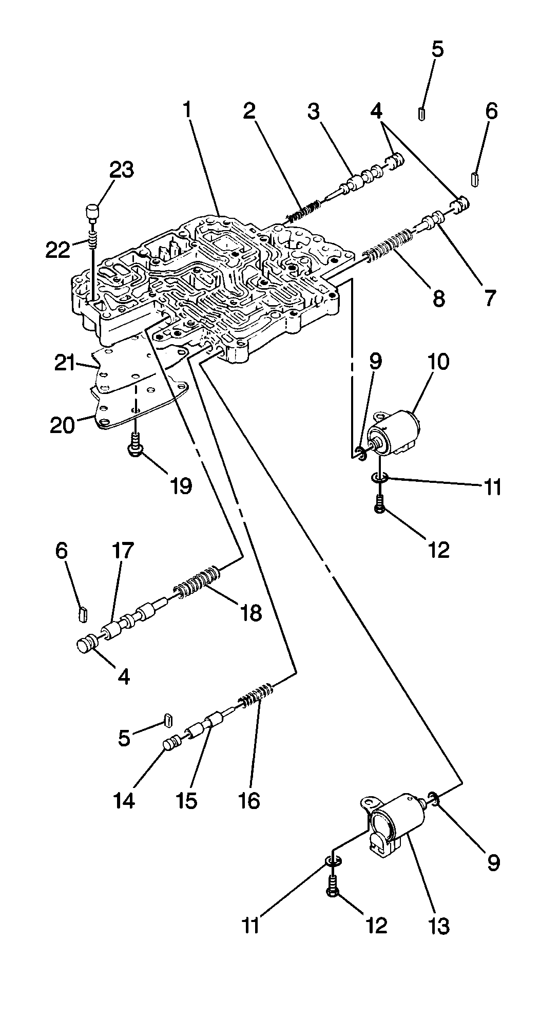
Removal Procedure
Tools Required
J 34673 Flat Gage
Bar
- Remove the 16 upper valve body bolts.
Important: The upper half of the valve body contains 4 check balls. Verify
that the upper value body is facing down.Separate the halves of the valve
body.Locate the 4 check balls. Reassemble the valve body, confirm that you
have positioned the check balls in the correct passages. Failure to observe
this procedure may result in transaxle shift failure.
- Disassemble the lower valve body from the upper valve body. Position
the upper valve body on the bottom and the lower valve body on the top.
- Remove the spacer plate and the gaskets.
- Remove the valve body and the accumulators. Refer to
Valve Body and Accumulators
.

- Remove the following from
the lower valve body (1):
| 5.1. | The 1 bolt and the direct clutch solenoid (10) |
| 5.2. | The 1 bolt and the second brake solenoid (13) |
| 5.3. | The No. 2 key of the valve body (6) |
| 5.4. | The shift valve plug (4) |
| 5.5. | The 2-3 shift valve (7) |
| 5.6. | The 2-3 shift valve spring (8) |
| 5.7. | The No. 1 key of the valve body (5) |
| 5.8. | The shift valve plug |
| 5.9. | The secondary regulator valve (3) |
| 5.10. | The secondary regulator valve spring (2) |
| 5.11. | The No. 1 key if the valve body |
| 5.12. | The B2 control valve plug (14) |
| 5.13. | The B2 control valve (15) |
| 5.14. | The B2 control valve spring (16) |
| 5.15. | The No. 2 key of the valve body |
| 5.16. | The shift valve plug |
| 5.17. | The 1-2 shift valve (17) |
| 5.18. | The 1-2 shift valve spring (23) |
| 5.19. | The cooler bypass valve (22) |
| 5.20. | The cooler bypass valve spring (21) |
| 5.21. | The 6 bolts, the lower valve body cover (19), and the lower gasket. |
- Clean the parts with a clean solvent, and dry the parts thoroughly.
- Inspect the lower valve body for distorted valve bores or for
damaged valve bores.
- Inspect the lower valve body for blocked fluid passages.
- Place J 34673
across the mating surface of the lower valve body.
- Rotate J 34673
. Inspect for surface warp every 30 degrees.
If the surface warp exists, replace the upper valve body.
- Inspect the valves, the springs, and the parts that are attached
for unusual wear. Replace the valves, the springs, and the parts, as necessary.
- Inspect the direct clutch and the O-rings of the second brake
solenoid for damage. Replace the direct clutch and the O-rings, as necessary.
Installation Procedure
Tools Required
J 36850 Transjel®
Transmission Assembly Lubricant

- Apply a thin coat of J 36850
to all parts prior to
assembly.
Notice: Use the correct fastener in the correct location. Replacement fasteners
must be the correct part number for that application. Fasteners requiring
replacement or fasteners requiring the use of thread locking compound or sealant
are identified in the service procedure. Do not use paints, lubricants, or
corrosion inhibitors on fasteners or fastener joint surfaces unless specified.
These coatings affect fastener torque and joint clamping force and may damage
the fastener. Use the correct tightening sequence and specifications when
installing fasteners in order to avoid damage to parts and systems.
- Lower the valve
body cover (19) and the new gasket onto the lower valve body (1). Secure
the cover with 6 bolts.
Tighten
Tighten the cover bolts (18) to 4 N·m (35 lb in).
- Install the following to the lower valve body:
| 3.1. | The cooler bypass valve spring (21) |
| 3.2. | The cooler bypass valve (22) |
| 3.3. | The 1-2 shift valve spring (23) |
| 3.4. | The 1-2 shift valve (17) |
| 3.5. | The shift valve plug (4) |
| 3.6. | The No. 2 key (6) of the valve body |
| 3.7. | The B2 control valve spring (16) |
| 3.8. | The B2 control valve (15) |
| 3.9. | The B2 control valve plug (14) |
| 3.10. | The No. 1 key (5) of the valve body |
| 3.11. | The secondary regulator valve spring (2) |
| 3.12. | The secondary regulator valve (3) |
| 3.13. | The shift valve plug |
| 3.14. | The No. 1 key of the valve body |
| 3.15. | The 2-3 shift valve spring (8) |
| 3.16. | The 2-3 shift valve (7) |
| 3.17. | The shift valve plug |
| 3.18. | The No. 2 key of the valve body |
- Install the second brake solenoid (13). Secure the second brake
solenoid with the 1 bolt.
Tighten
Tighten the retaining bolt to 4 N·m (35 lb in).
- Install the direct clutch solenoid (10) into the lower valve body.
Secure the solenoid with the 1 bolt.
Tighten
Tighten the retaining bolt of the direct clutch solenoid to 4 N·m
(35 lb in).
- Inspect all of the valves in order to ensure smooth operation.
- Install the gaskets and the spacer plate.
- Position the lower valve body with the upper valve body.
- Install the 16 valve body bolts. Refer to
Valve Body and Accumulators
- Install the valve body assembly to the transmission. Refer to
Valve Body and Accumulators


