For 1990-2009 cars only
Removal Procedure
- Disconnect the negative battery cable.
- Place the shift selector into the N position.
- Remove the 2 screws and the selector knob (1) from the selector lever (6).
- Remove the 4 screws and the center console from the vehicle.
- Unsnap the select indicator cover from the selector housing.
- Remove the connector of the shift lock solenoid from under the carpet.
- Disconnect the illumination lamp and shiftlock solenoid connectors.
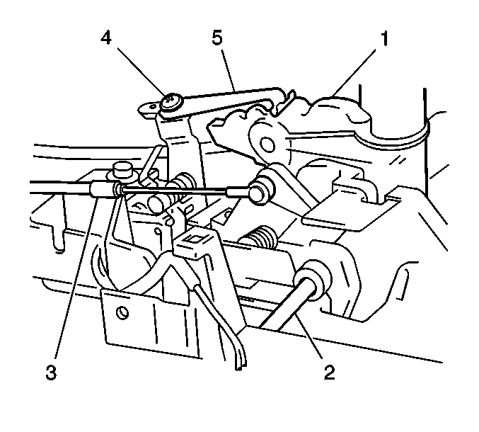
- Disconnect the interlock cable end from the key interlock cam.
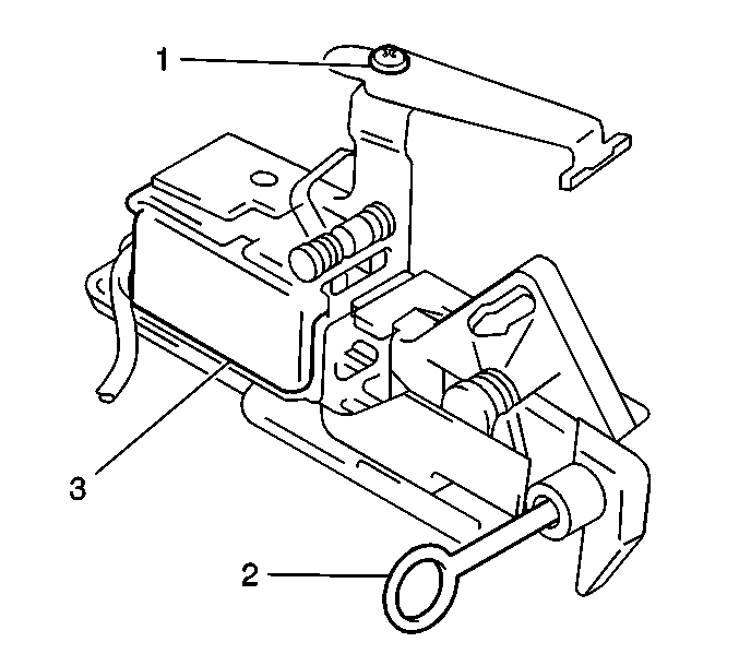
- Remove the shift lock solenoid assembly (3) from the housing.
Caution: Unless directed otherwise, the ignition and start switch must be in the OFF or LOCK position, and all electrical loads must be OFF before servicing any electrical component. Disconnect the negative battery cable to prevent an electrical spark should a tool or equipment come in contact with an exposed electrical terminal. Failure to follow these precautions may result in personal injury and/or damage to the vehicle or its components.

Installation Procedure
- Loosen the location spring screw (3).
- With the selector lever shifted to the N position, install the shiftlock solenoid assembly to the housing.
- Align the location spring end with the guide groove and tighten the spring screw (3).
- Apply some lithium grease GM P/N 1051344 to the guide groove (2) and the detent pin.
- Install the interlock cable end to the cam.
- Connect the shiftlock solenoid and the illumination lamp connectors.
- Install the connector of the shift lock solenoid under the carpet.
- Install the select indicator cover to the selector housing.
- Install the center console and the 4 screws.
- Install the selector knob the 2 screws.
- Connect the negative battery cable.
- Confirm that the brake key interlock system operates properly.

