Circuit Description
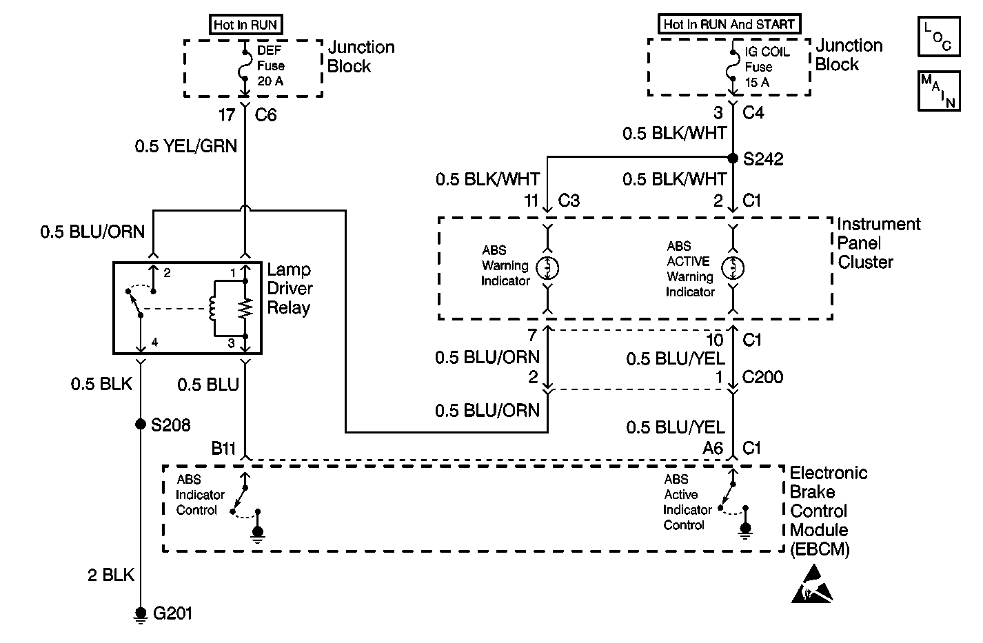
The Electronic Brake Control Module (EBCM) controls the operation of the amber ABS indicator lamp by means of a lamp driver relay.
The amber ABS indicator lamp is connected to the IG COIL fuse. This circuit is hot in ON and START ignition switch positions.
When the lamp driver relay is in the OFF state, the lamp driver relay grounds the amber ABS indicator lamp. This causes the amber ABS indicator lamp to turn ON.
When the EBCM commands OFF the ABS indicator, the EBCM turns ON the lamp driver relay by grounding the ABS indicator control circuit. This causes the lamp driver relay to open the path to ground, turning OFF the amber ABS indicator lamp.
When the ignition switch is turned to the ON position, the EBCM turns ON the ABS indicator for 3 seconds for a bulb check. Whenever a malfunction is detected within the ABS system, the EBCM tuns ON the ABS indicator, notifying the driver that ABS needs to be serviced. If the EBCM commands the red BRAKE warning indicator ON due to an ABS malfunction that may degrade base braking operation and cannot do so, the ABS indicator will flash to indicate the serious nature of the problem.
Diagnostic Aids
The following conditions may cause a malfunction:
| • | Short to ground between the lamp driver relay and the amber ABS indicator lamp |
| • | Open circuit or high resistance between the EBCM and the lamp driver relay |
| • | Open DEF fuse |
| • | Open coil or constantly closed contacts of the lamp driver relay |
Use the Lamp Test function of the Scan Tool in order to turn the indicator on while looking for an intermittent malfunction in the ABS warning indicator circuitry.
Thoroughly inspect any circuitry that may cause the intermittent complaint for the following conditions:
| • | Backed out terminals |
| • | Improper mating |
| • | Broken locks |
| • | Improperly formed or damaged terminals |
| • | Poor terminal-to-wiring connections |
| • | Physical damage to the wiring harness |
Step | Action | Value(s) | Yes | No |
|---|---|---|---|---|
|
Important: Zero the J 39200 test leads before making any resistance measurements. Refer to the J 39200 user's manual. | ||||
1 | Was A Diagnostic System Check-ABS performed? | -- | ||
2 |
Do not start the engine. Does the Scan Tool indicate that the ABS Warning Indicator is ON? | -- | ||
3 | Disconnect the Lamp Driver Relay connector. Does the ABS Warning Indicator turn OFF? | -- | ||
4 |
Is the resistance within the specified range? | OL (Infinite) | ||
5 | Replace the EBCM. Refer to Electronic Brake Control Module Replacement . Is the repair complete? | -- | -- | |
6 | Replace the Lamp Driver Relay. Refer to Lamp Driver Relay Replacement . Is the repair complete? | -- | -- | |
7 | Repair the short to ground in the BLU/ORN wire between the IPC and the Lamp Driver Relay. Is the repair complete? | -- | -- | |
8 | Repair the instrument panel cluster. Refer to Instrument Cluster System Check in Instrument Panel, Gauges and Console. Is the repair complete? | -- | -- | |
