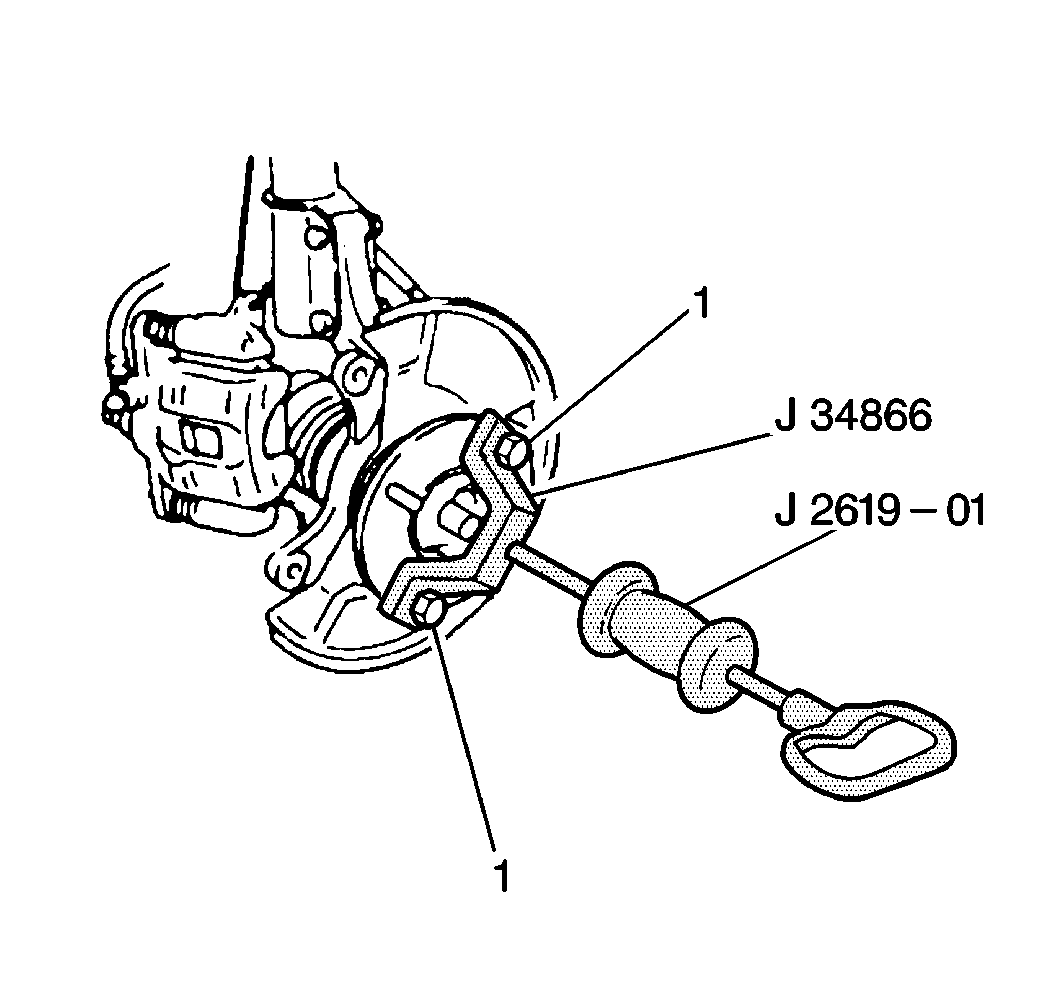
- Apply a light coat of
wheel bearing grease
GM P/N 1051344, or equivalent, to the outside of the hub shaft.
- If a new knuckle is being installed, install the hub and the outer
bearing. Refer to
Front Wheel Bearing and Hub Replacement
Notice: Use the correct fastener in the correct location. Replacement fasteners
must be the correct part number for that application. Fasteners requiring
replacement or fasteners requiring the use of thread locking compound or sealant
are identified in the service procedure. Do not use paints, lubricants, or
corrosion inhibitors on fasteners or fastener joint surfaces unless specified.
These coatings affect fastener torque and joint clamping force and may damage
the fastener. Use the correct tightening sequence and specifications when
installing fasteners in order to avoid damage to parts and systems.
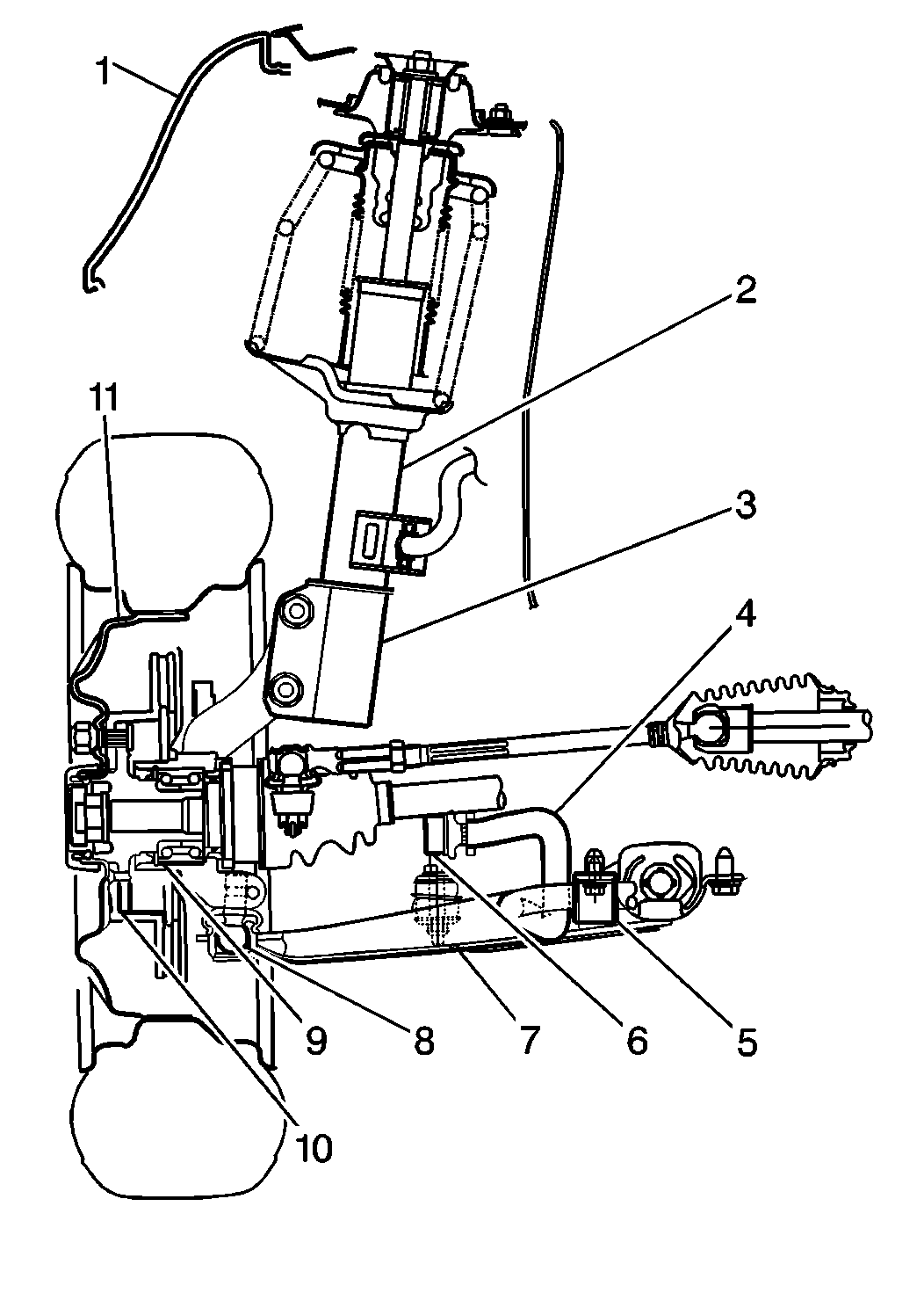
- Install the steering
knuckle to the strut (3). Secure the steering knuckle with two strut-to-knuckle
bolts and nuts.
Tighten
Tighten the strut-to-knuckle bolts and nuts to 80 N·m (59 lb ft).
- Install the ball stud to knuckle. Secure with the bolt and nut.
Tighten
Tighten the ball joint nut and bolt to 60 N·m (44 lb ft).
- Install the tie rod end to the knuckle. Secure with the castle
nut and cotter pin.
Tighten
Tighten the tie rod end castle nut to 43 N·m (32 lb ft).
- Install the wheel drive shaft nut and washer.
- Refer to
Brake Caliper Replacement
in order to install the following:
- Secure the items with the drive axle nut.
Tighten
Tighten the drive axle nut to 175 N·m (129 lb ft).
- Install stake the wheel drive shaft nut using a hammer and punch.
- Install the wheel speed electrical connector to sensor, for ABS
equipped vehicles.
- Install the wheel speed sensor to knuckle. Secure with one bolt,
for ABS equipped vehicles.
Tighten
Tighten the wheel speed sensor retaining bolt to 10 N·m
(89 lb in).
- Install the tire and wheel assembly. Refer to
Tire and Wheel Removal and Installation
in Tires
and Wheels.
- Lower the vehicle.


