For 1990-2009 cars only
Removal Procedure
- Remove the battery tray. Refer to Battery Tray Replacement.
- Remove the transmission range select lever cable and bracket. Refer to Range Selector Lever Cable Bracket Replacement.
- Drain the transmission fluid. Refer to Transmission Fluid Replacement.
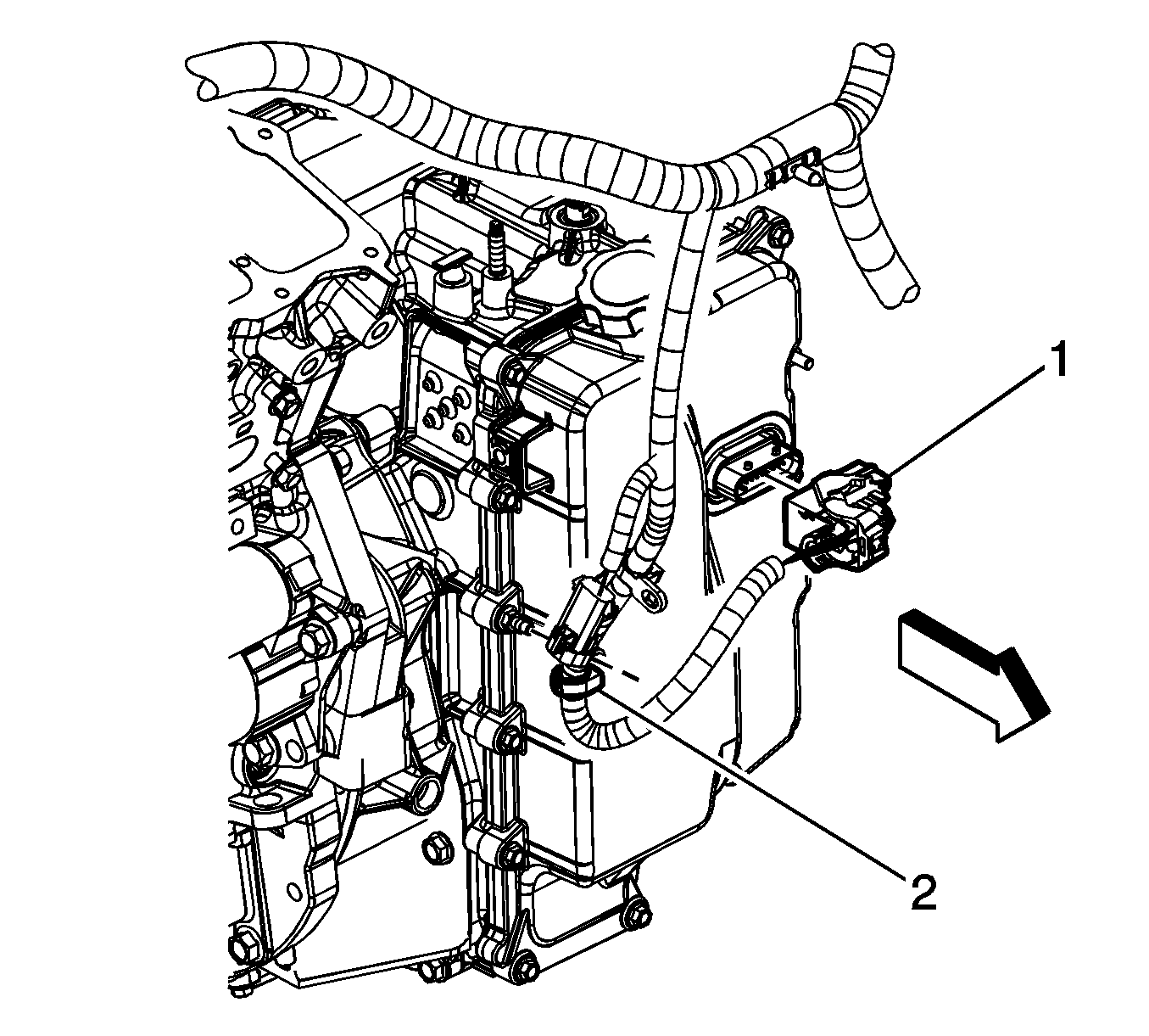
- Remove the wire harness retainer (2) from the control valve body cover stud.
- Disconnect the control valve body transmission control module (TCM) electrical connector (1).
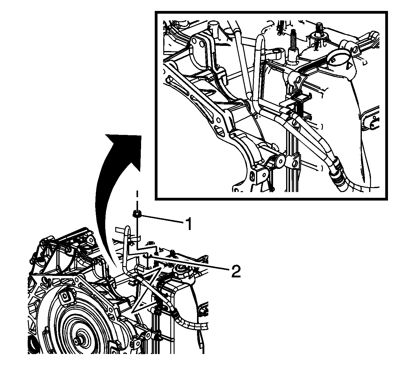
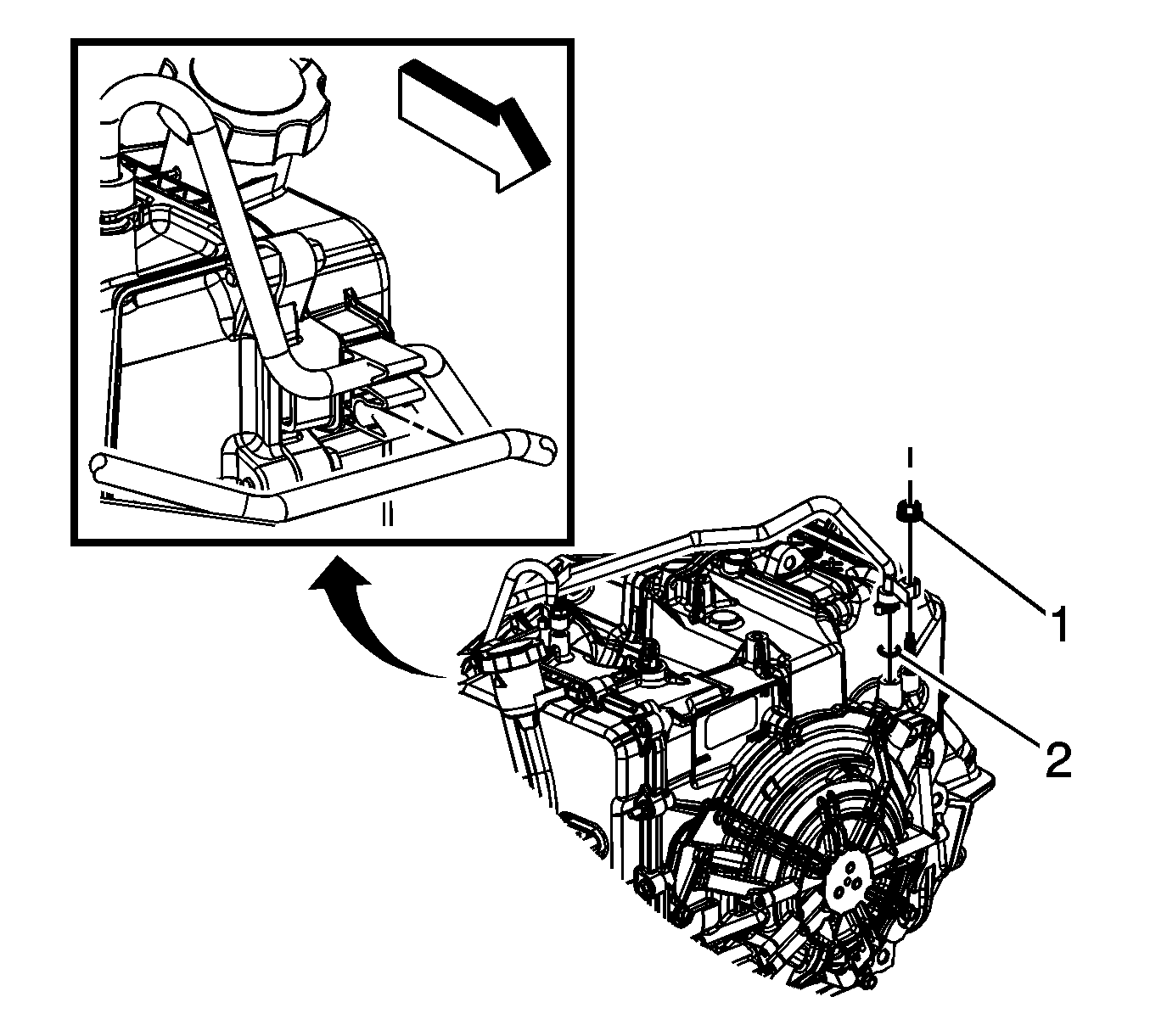
- Remove the transmission fluid cooler pipe retainer nut (1).
- Remove the transmission fluid cooler inlet hose and seal (2) from the transmission.
- Plug and/or cap the hose and transmission to prevent contamination.
- Remove the transmission fluid cooler pipe retainer nut (1).
- Remove the transmission fluid cooler outlet hose and seal (2) from the transmission.
- Plug and/or cap the hose and transmission to prevent contamination.
- Disconnect both pipes from the retainer.
- Install the engine support fixture. Refer to Engine Support Fixture
- Remove the rear transmission mount (2) from the transmission. Refer to Transmission Rear Mount Replacement.
- Remove the front transmission mount from the transmission. Refer to Transmission Front Mount Replacement
- Remove the left transmission mount from the transmission. Refer to Transmission Mount Replacement - Left Side
- Remove the upper transmission to engine bolts (1, 2).
- Remove the frame. Refer to Frame Replacement.
- Disconnect the wheel drive shafts from the transmission. Refer to Wheel Drive Shaft Replacement.
- Remove the intermediate drive shaft. Refer to Front Wheel Drive Intermediate Shaft Replacement.
- Remove the starter. Refer to Starter Replacement.
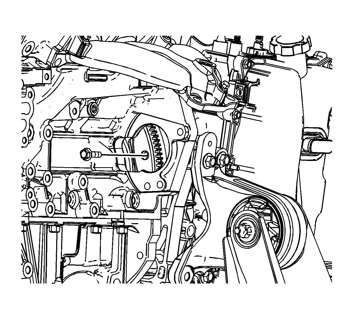
- Mark the relationship of the flywheel to the torque converter for reassembly.
- Remove the torque converter to flywheel bolts.
- Use a transmission jack in order to support the transmission.
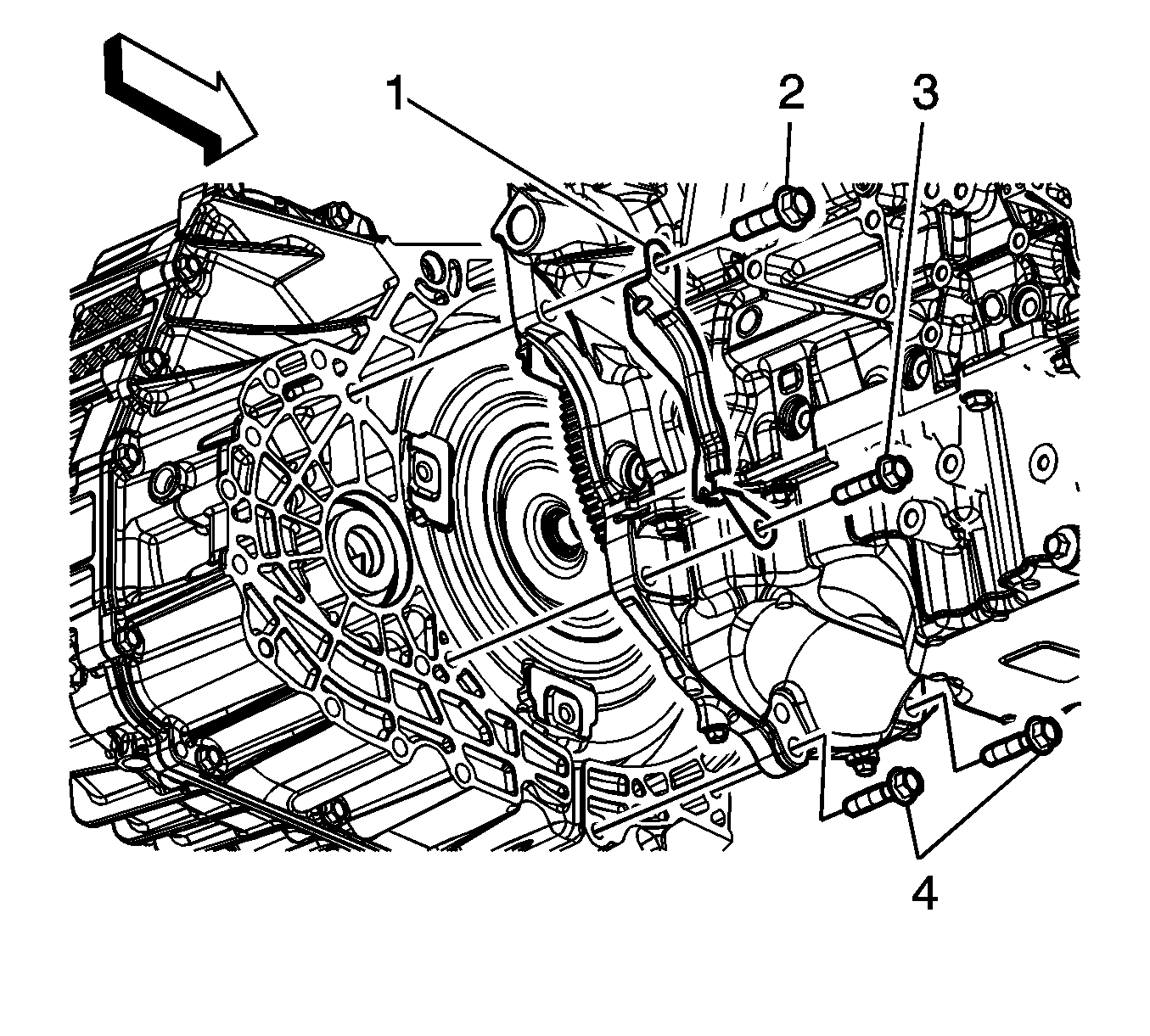
- Remove the flywheel inspection cover bolts (2, 3).
- Remove the flywheel inspection cover (1).
- Remove the remaining transmission bolts (4).
- Separate the transmission from the engine.
- Lower the transmission with the transmission jack far enough to remove the transmission.
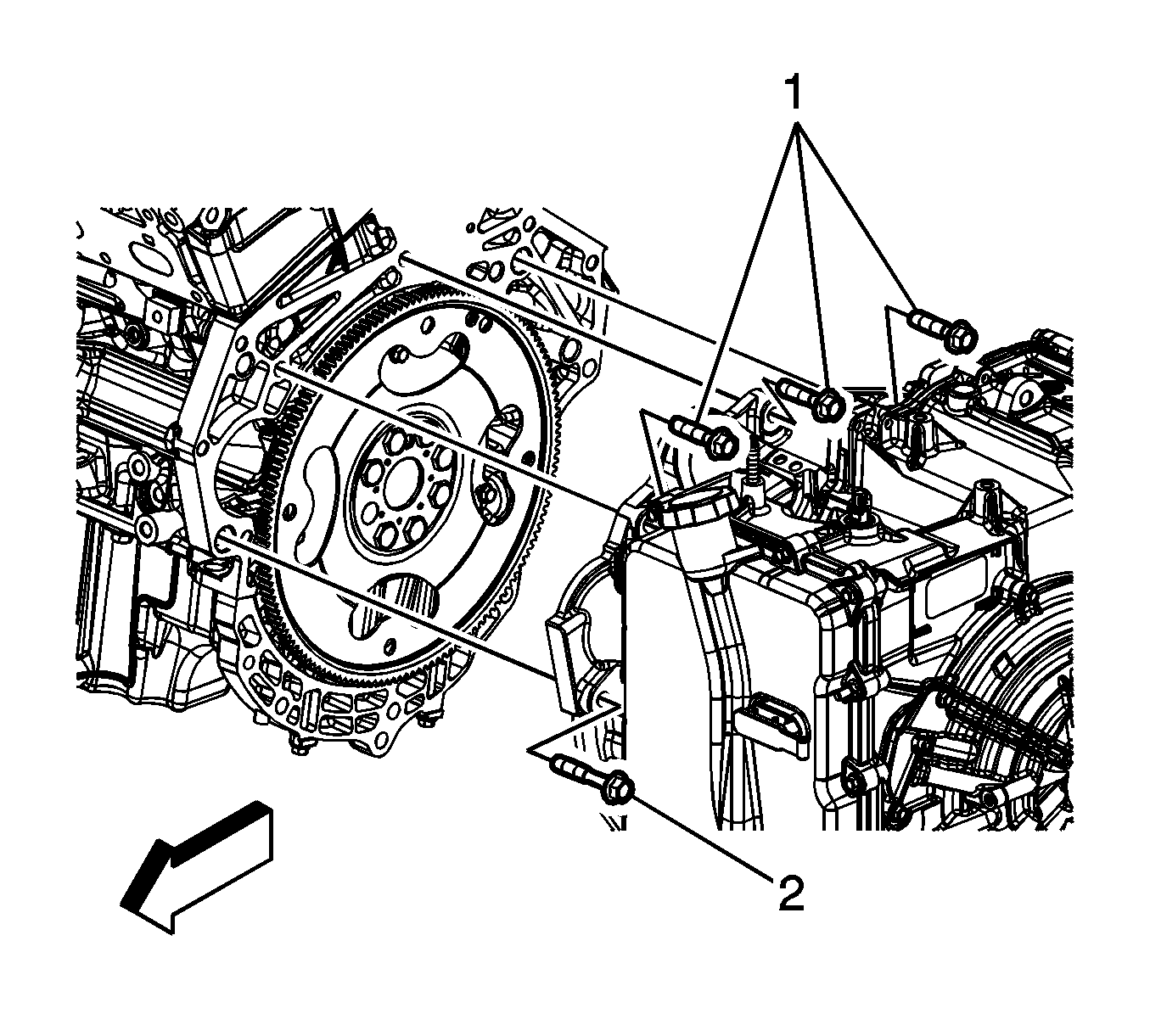
Note: Insure the torque converter remains securely in place on the transmission input shaft while separating and removing the transmission.
Installation Procedure
- Raise the transmission with the transmission jack and position the transmission to the engine.
- Install the transmission bolts (4) and tighten to 75 N·m (55 lb ft).
- Install the flywheel inspection cover (1).
- Install the flywheel inspection cover bolts (2, 3) and tighten to 75 N·m (55 lb ft).
- Remove the transmission jack.
- Install the torque converter to flywheel bolts and tighten to 62 N·m (46 lb ft).
- Install the starter. Refer to Starter Replacement.
- Install the front transmission mount to the transmission. Refer to Transmission Front Mount Replacement.
- Install the rear transmission mount to the transmission. Refer to Transmission Rear Mount Replacement.
- Install the left transmission mount to the transmission. Refer to Transmission Mount Replacement - Left Side
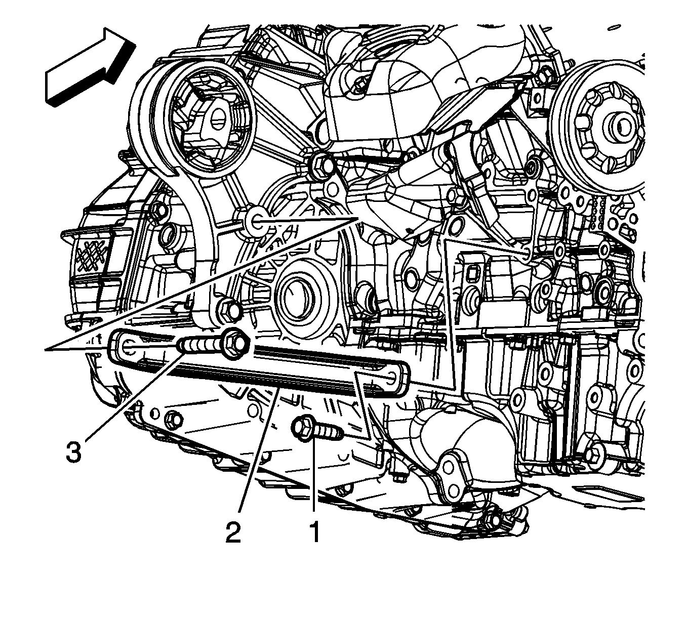
- Install the transmission brace (2).
- Install the transmission brace bolts (1, 3) and tighten to 50 N·m (37 lb ft).
- Install the intermediate drive shaft. Refer to Front Wheel Drive Intermediate Shaft Replacement.
- Install the wheel drive shafts to the transmission. Refer to Wheel Drive Shaft Replacement.
- Install the frame. Refer to Frame Replacement.
- Install the upper transmission to engine bolt (1, 2) and tighten to 75 N·m (55 lb ft).
- Remove the engine support fixture.
- Install the transmission fluid cooler outlet hose and seal (2) to the transmission.
- Install the transmission fluid cooler pipe retainer nut (1) and tighten to 22 N·m (16 lb ft).
- Install the transmission fluid cooler inlet hose and seal (2) to the transmission.
- Install the transmission fluid cooler pipe retainer nut (1) and tighten to 22 N·m (16 lb ft).
- Connect the control valve body TCM electrical connector (1).
- Install the wire harness retainer (2) to the control valve body cover stud and tighten the nut to 12 N·m (106 lb in).
- Install the transmission range select lever cable and bracket. Refer to Range Selector Lever Cable Bracket Replacement.
- Install the battery tray. Refer to Battery Tray Replacement.
- Adjust the automatic transmission range selector lever cable. Refer to Range Selector Lever Cable Adjustment.
- Fill the transmission with fluid. Refer to Transmission Fluid Replacement.
- For transmission control module programming and setup, refer to Control Module References.
- Perform the service fast learn adapt procedure. Refer to Service Fast Learn Adapts.
- Road test the vehicle.
Caution: Refer to Fastener Caution in the Preface section.


Note: If reusing the torque converter bolts, clean the threads and apply LOCTITE™242, GM P/N 12345382 (Canadian P/N 10953489) or equivalent to the threads prior to installation.


Note: After an internal transmission repair or internal part replacement the service fast learn adapt procedure should be performed.
