Special Tools
J 45722 Fuel Sender Lock Ring Wrench
Removal Procedure
Note: Clean the fuel and evaporative emission (EVAP) connections and surrounding areas prior to disconnecting the lines in order the avoid possible system contamination.
- Relieve the fuel system pressure. Refer to Fuel Pressure Relief.
- Drain the fuel tank. Refer to Fuel Tank Draining.
- Raise and support the vehicle. Refer to Lifting and Jacking the Vehicle.
- Disconnect the fuel tank fuel pump module wiring harness electrical connector (1) from body wiring harness electrical connector (2).
- Remove the body wiring harness electrical connector clip (3) from the EVAP canister.
- Disconnect the body wiring harness electrical connector (2) from the rear antilock brake system (ABS) wiring harness electrical connector (1).
- Remove the rear ABS wiring harness electrical connector (3) clip from the EVAP canister.
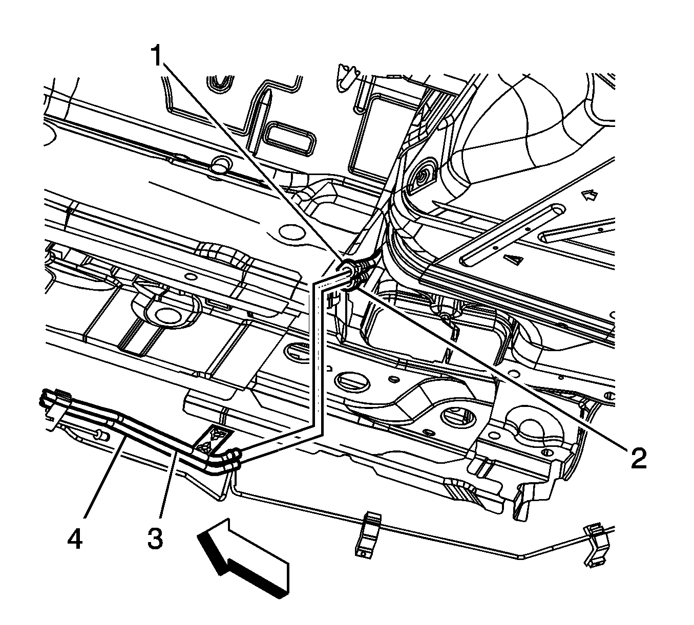
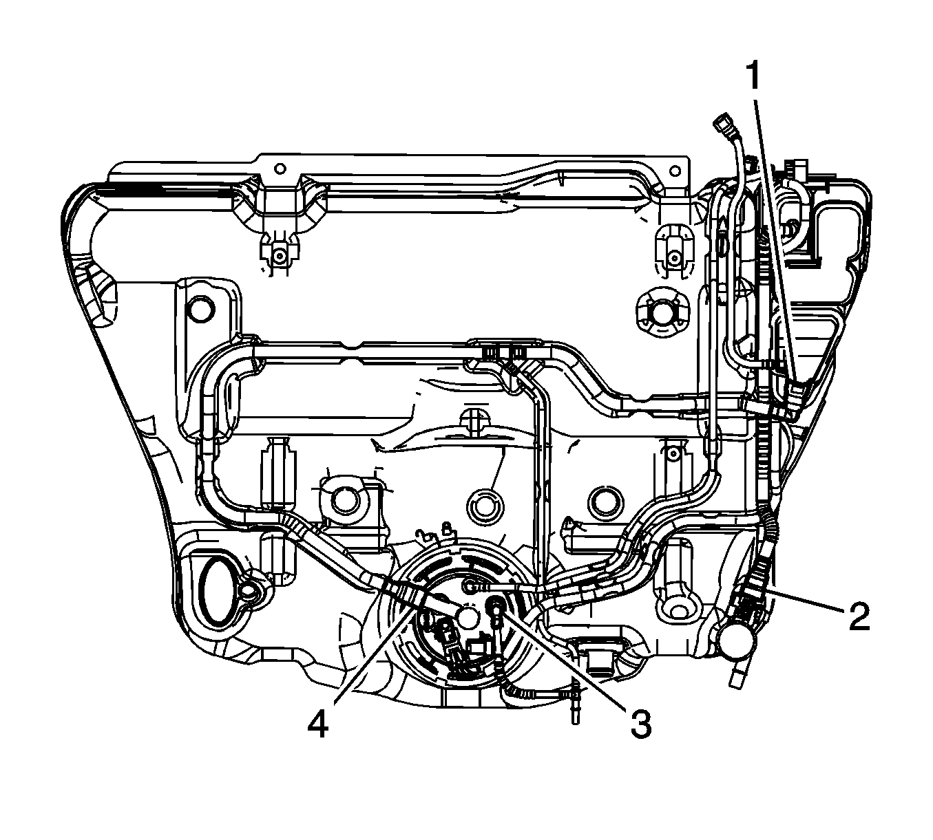
- Disconnect the fuel tank fuel feed pipe quick connect fitting (1) from the chassis fuel feed pipe (3). Refer to Plastic Collar Quick Connect Fitting Service.
- Disconnect the fuel tank EVAP pipe quick connect fitting (2) from the chassis EVAP pipe (4). Refer to Plastic Collar Quick Connect Fitting Service.
- Cap the chassis fuel and EVAP pipes in order to prevent possible fuel and/or EVAP system contamination.
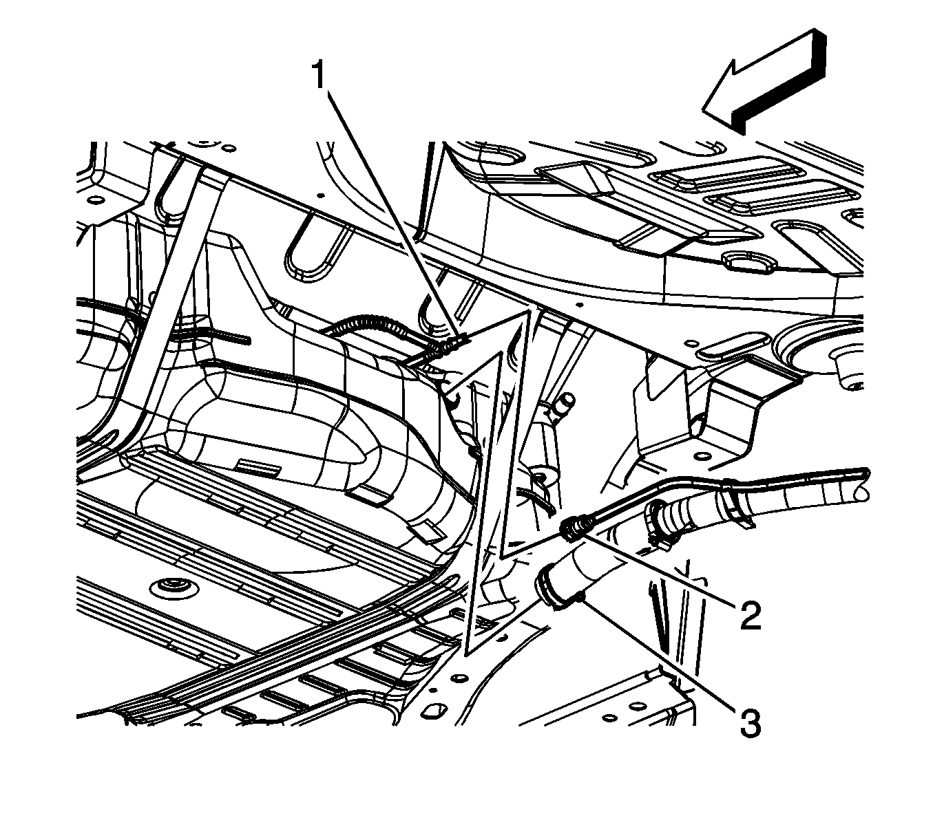
- Disconnect the fuel tank fill EVAP emission pipe quick connect fitting (2) from the fuel tank vent pipe (1). Refer to Plastic Collar Quick Connect Fitting Service.
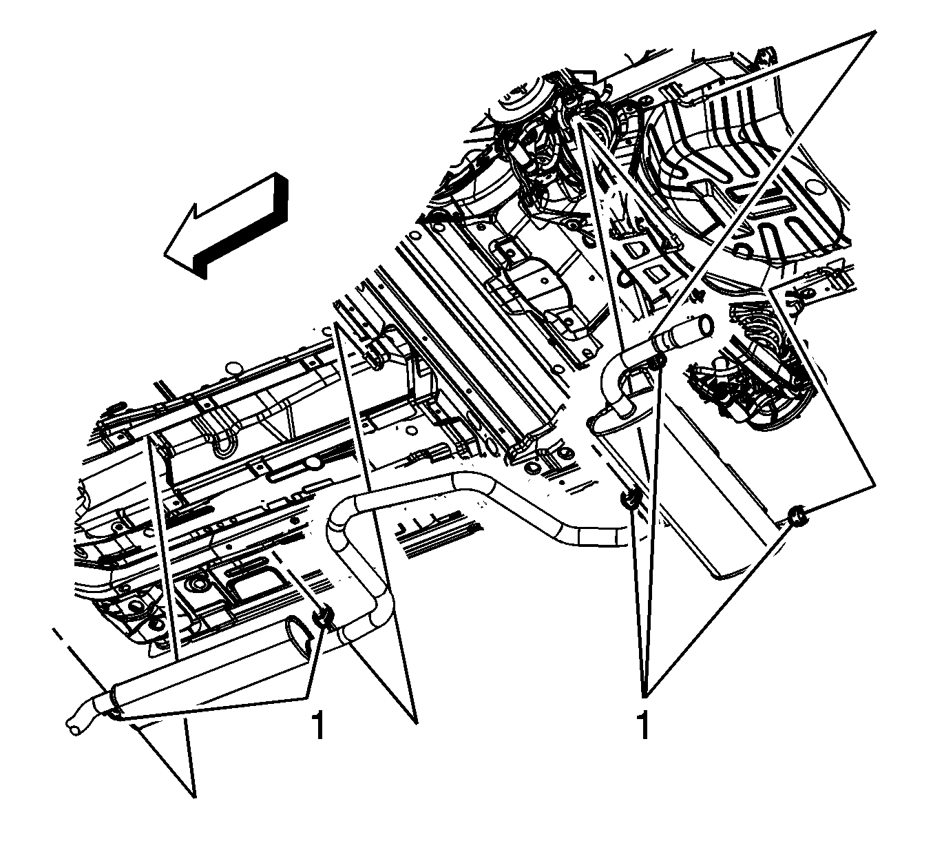
- Place a jackstand under the muffler assembly.
- With the aid of an assistant, separate the muffler insulators (1) from the underbody hangers.
- Slowly lower the muffler assembly allowing it to rest on the jackstand. If this is not possible, remove the muffler assembly. Refer to Exhaust Muffler Replacement.
- Have assistants support either side of the fuel tank.
- Place a suitable adjustable jack under the fuel tank, and have the assistants rest the fuel tank on the adjustable jack.
- Remove fuel tank strap bolts and straps.
- If applicable, in order to clear the muffler assembly, slowly lower the right side of the fuel tank.
- Once the tank is clear of the right frame rail, lower the fuel tank down and remove forward toward the right side of the vehicle.
- If replacing the fuel tank, proceed to the disassembly procedure, if not proceed to the Installation Procedure.



Disassembly Procedure
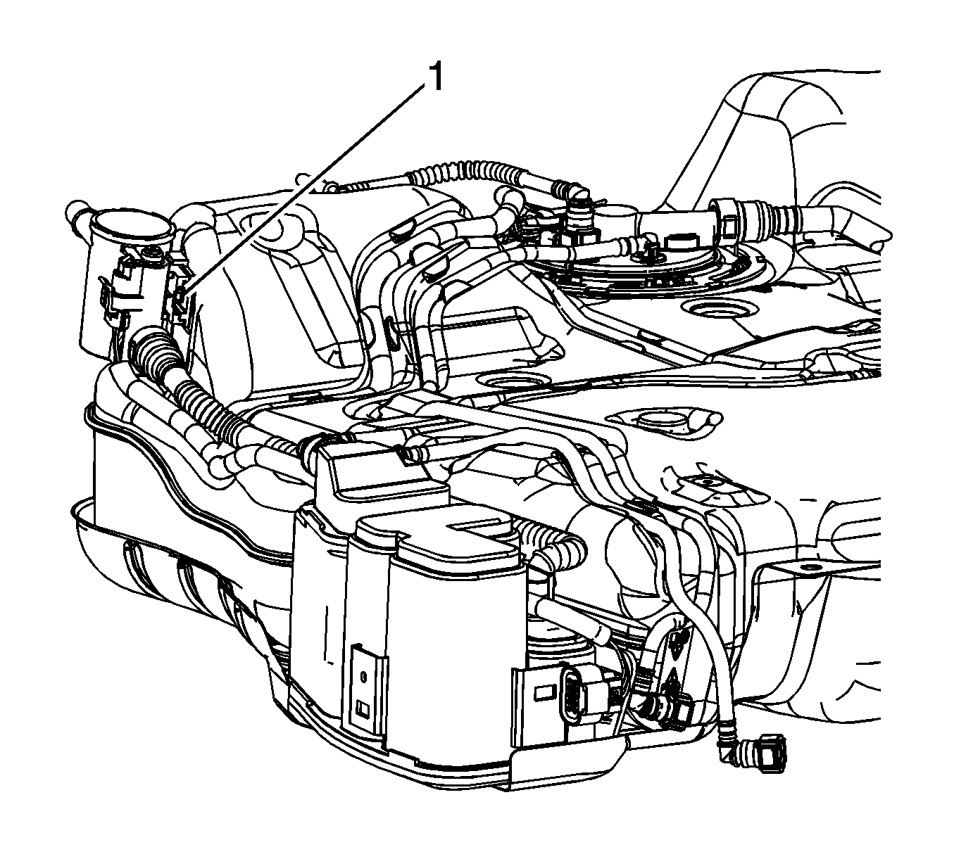
- Disconnect the fuel tank fuel pump module wiring harness electrical connectors (1, 2) from the fuel pressure sensor and the module.
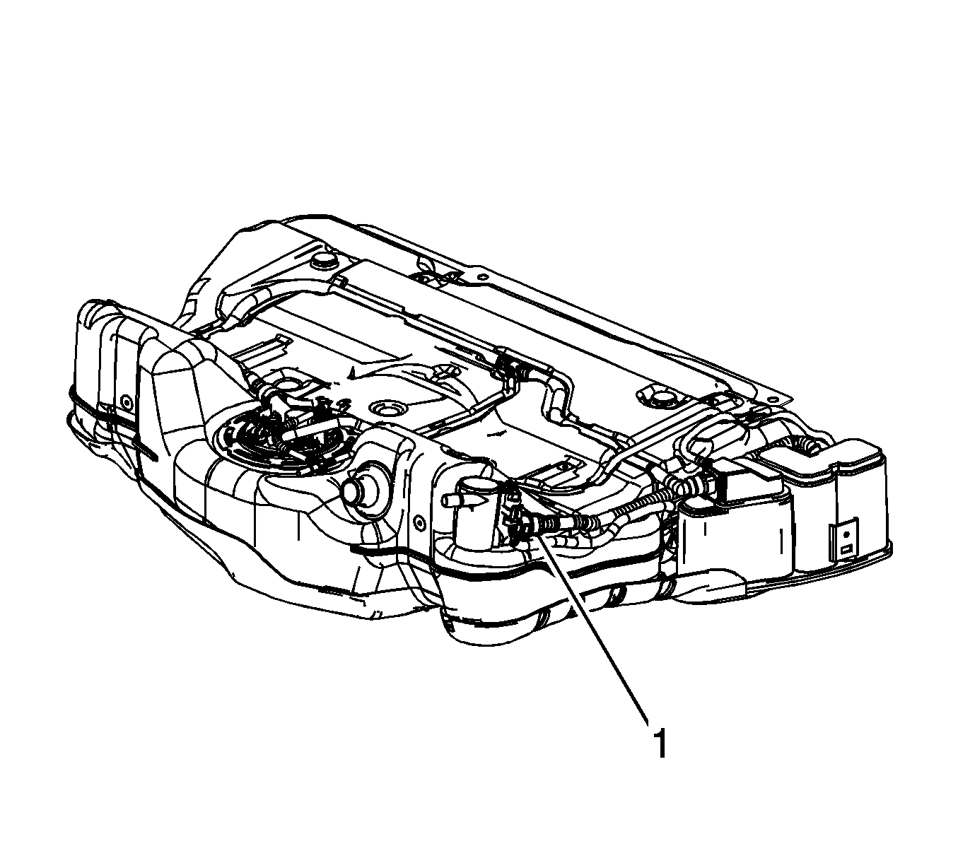
- Disconnect the fuel tank fuel pump module wiring harness electrical connector (1) from the EVAP canister vent solenoid.
- Disconnect the fuel tank vent pipe quick connect fitting (1) from the EVAP canister. Refer to Plastic Collar Quick Connect Fitting Service.
- Disconnect the fuel tank vent pipe quick connect fittings (3, 4) from the module. Refer to Plastic Collar Quick Connect Fitting Service.
- Remove the EVAP emission canister purge pipe from the retaining features (3) built into the fuel tank.
- Remove the fuel tank fuel pump module wiring harness from the retaining features (5) built into the fuel tank.
- Remove the fuel tank vent pipe from the retaining features (1) built into the fuel tank.
- Remove the fuel feed pipe from the retaining features (2, 4) built into the fuel tank.
- Insert and gently push a small flat-bladed tool between the EVAP canister vent solenoid and the retaining bracket, disengaging the retaining tab (1).
- Remove the EVAP canister bolt.
- Remove the fuel tank fuel pump module wiring harness from around the EVAP canister.
- Remove the EVAP canister and EVAP canister vent solenoid as an assembly.
- Remove the fuel tank fuel pump module wiring harness.
- Remove the fuel tank vent pipe from the fuel tank.
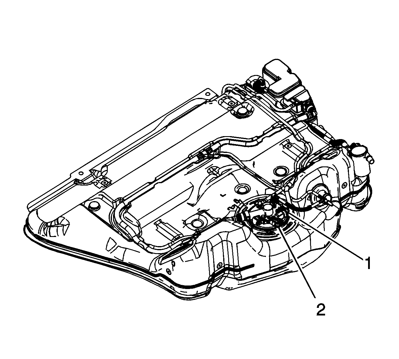
- Install the J 45722 to the fuel pump module lock ring.
- Using the J 45722 and a long breaker-bar, rotate the lock ring in a counterclockwise direction in order to unlock the lock ring.
- Remove the J 45722 from the fuel pump module lock ring.
- Lift the fuel pump module up slightly in order to disconnect the fuel tank vent pipe quick connect fitting (1) from the module cover. Refer to Plastic Collar Quick Connect Fitting Service.
- Raise the fuel pump module up from the fuel tank. Tilt the module in order to allow the fuel level sensor arm and float to clear the module opening.
- Remove the fuel pump module.
- Remove and discard the fuel pump module seal.
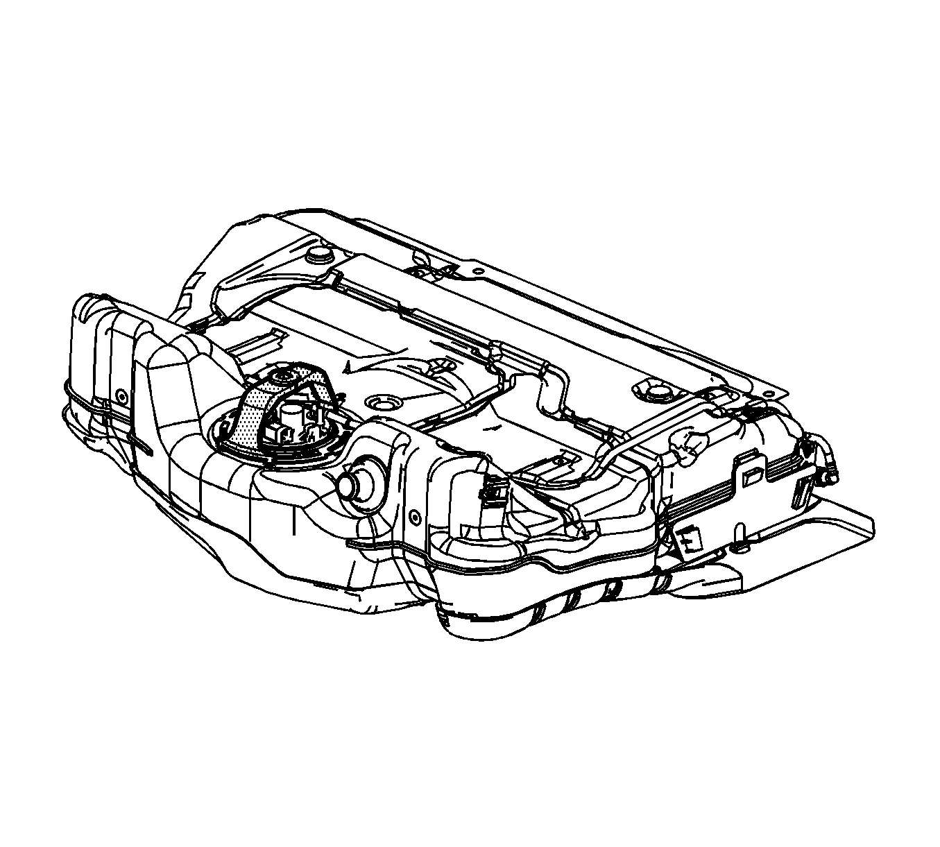
- Remove the fuel tank shield retainers and shield.
- Clean the fuel pump module sealing surfaces.



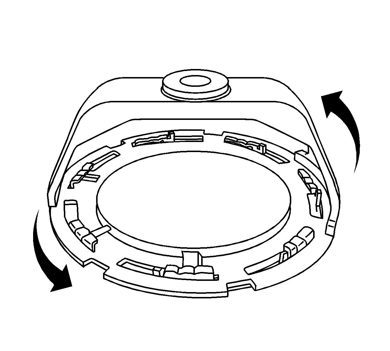
Caution: Avoid damaging the lock ring. Use only J-45722 to prevent damage to the lock ring.
Caution: Do Not handle the fuel sender assembly by the fuel pipes. The amount of leverage generated by handling the fuel pipes could damage the joints.
Note: Do NOT use impact tools. Significant force will be required to release the lock ring. The use of a hammer and screwdriver is not recommended. Secure the fuel tank in order to prevent fuel tank rotation.
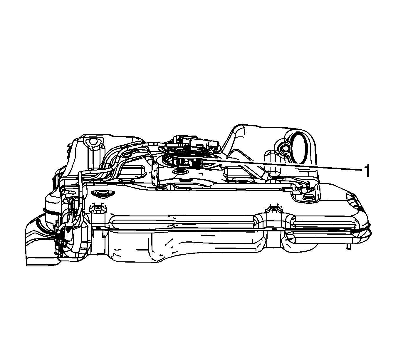
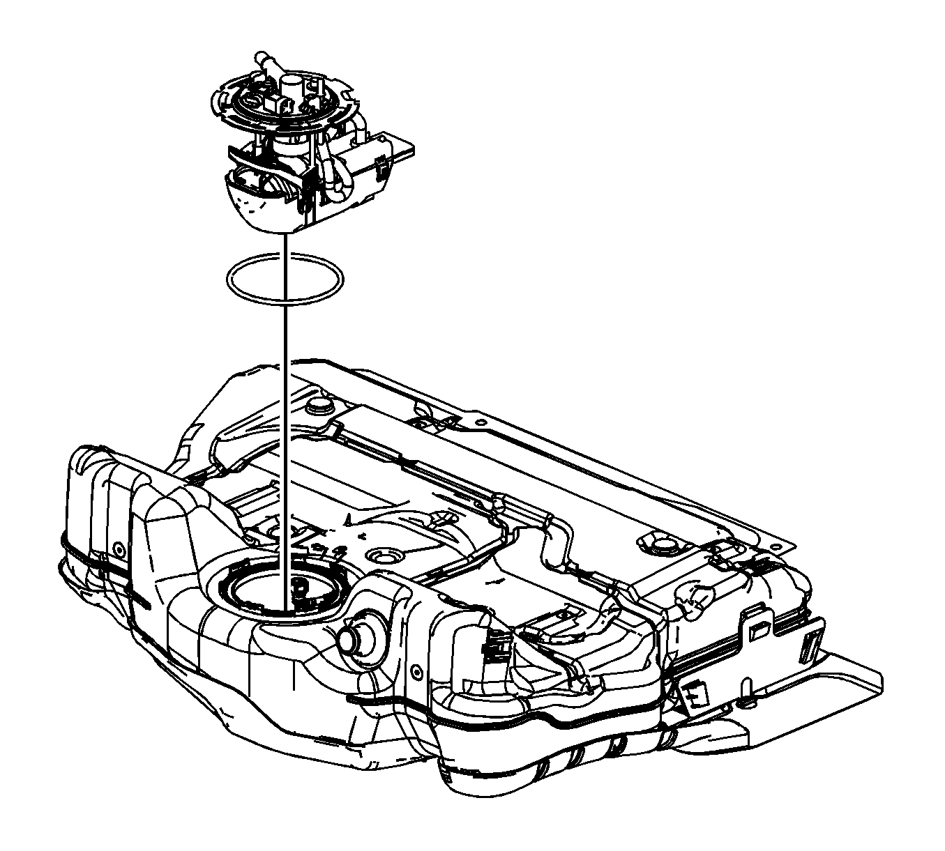

Warning: Drain the fuel from the fuel sender assembly into an approved container in order to reduce the risk of fire and personal injury. Never store the fuel in an open container
Assembly Procedure
Warning: In order to reduce the risk of fire and personal injury that may result from a fuel leak, always replace the fuel sender gasket when reinstalling the fuel sender assembly.
Note:
• Some lock rings were manufactured with "DO NOT REUSE" stamped into them. These lock rings may be reused if they are not damaged or warped. • Inspect the lock ring for damage due to improper removal or installation procedures. If damage is found, install a NEW fuel pump module. • Inspect the lock ring for flatness as best as possible. If the lock ring is warped, replace the fuel pump module.
- Install the fuel tank shield and retainers.
- Clean any contamination from the male pipe ends of the fuel pump module.
- Place a NEW fuel tank module seal onto the fuel tank.
- Insert the fuel pump module into the fuel tank allowing the sensor arm and float to clear the module opening.
- Lower the module down into the fuel tank until the fuel tank vent pipe quick connect fitting can be connected.
- Connect the fuel tank vent pipe quick connect fitting (1) at the module cover. Refer to Plastic Collar Quick Connect Fitting Service.
- Press the fuel tank module downward.
- Install the J 45722 to the fuel pump module lock ring.
- Using the J 45722 and a long breaker-bar, rotate the lock ring in a clockwise direction in order the lock the lock ring.
- Remove the J 45722 from the fuel pump module lock ring.
- Install the EVAP canister and the EVAP canister vent solenoid as an assembly. Slide the EVAP canister vent solenoid onto the fuel tank bracket until the retaining tab is engaged.
- Install the EVAP canister bolt.
- Install the fuel tank fuel pump module wiring harness.
- Connect the fuel tank fuel pump module wiring harness electrical connector (1) to the EVAP canister vent solenoid.
- Connect the fuel tank fuel pump module wiring harness electrical connectors (1, 2) to the fuel pressure sensor and the module.
- Install the fuel tank vent pipe to the fuel tank.
- Connect the fuel tank vent pipe quick connect fitting (1) to the EVAP canister. Refer to Plastic Collar Quick Connect Fitting Service.
- Connect the fuel tank vent pipe quick connect fittings (3, 4) to the module. Refer to Plastic Collar Quick Connect Fitting Service.
- Install the fuel feed pipe to the retaining features (2, 4) built into the fuel tank.
- Install the fuel tank vent pipe to the retaining features (1) built into the fuel tank.
- Install the fuel tank fuel pump module wiring harness to the retaining features (5) built into the fuel tank.
- Install the EVAP emission canister purge pipe to the retaining features (3) built into the fuel tank.


Note: Ensure that the lock ring is installed with the correct side facing upward. A correctly installed lock ring will only turn in a clockwise direction.

Caution: Refer to Fastener Caution in the Preface section.
Tighten
Tighten the bolt to 3.5 N·m (31 lb in).


Installation Procedure
- Have assistants support either side of the fuel tank.
- If applicable, begin to install the right side of the fuel tank over the muffler assembly.
- If applicable, raise the right side of the fuel tank into position inboard of the right frame rail. Use care in feeding the fuel feed, EVAP line wiring harness over the muffler assembly.
- If applicable and the muffler assembly was removed, have assistants raise the fuel tank into position.
- Install fuel tank straps and bolts.
- Raise the muffler assembly into position if applicable, otherwise install the muffler assembly. Refer to Exhaust Muffler Replacement.
- With the aid of an assistant, install the muffler insulators (1) to the underbody hangers.
- Remove the jackstand from under the muffler assembly.
- Install the fuel fill pipe hose to the fuel tank.
- Connect the fuel tank fill EVAP emission pipe quick connect fitting (2) to the fuel tank vent pipe (1). Refer to Plastic Collar Quick Connect Fitting Service.
- Tighten the fuel fill pipe hose clamp (3) at the fuel tank.
- Remove the caps from the fuel and EVAP pipes.
- Connect the fuel tank EVAP pipe quick connect fitting (2) to the chassis EVAP pipe (4). Refer to Plastic Collar Quick Connect Fitting Service.
- Connect the fuel tank fuel feed pipe quick connect fitting (1) to the chassis fuel feed pipe (3). Refer to Plastic Collar Quick Connect Fitting Service.
- Install the rear ABS wiring harness electrical connector (2) clip to the EVAP canister.
- Connect the body wiring harness electrical connector (1) to the rear ABS wiring harness electrical connector (2).
- Install the body wiring harness electrical connector clip (3) to the underbody.
- Connect the fuel tank fuel pump module wiring harness electrical connector (1) to the body wiring harness electrical connector (2).
- Lower the vehicle.
- Refill the fuel tank.
- Tighten the fuel fill cap.
- Inspect for leaks.

Tighten
Tighten the bolts to 20 N·m (15 lb ft).


Tighten
Tighten the clamp to 4 N·m (35 lb in).


| 22.1. | Turn ON the ignition, with the engine OFF for 10 seconds. |
| 22.2. | Turn OFF the ignition for 10 seconds. |
| 22.3. | Turn ON the ignition, with the engine OFF. |
| 22.4. | Inspect for fuel leaks. |
