For 1990-2009 cars only
Tools Required
J 39194-B Heated Oxygen Sensor Socket
Removal Procedure
- Remove the air intake tube. Refer to Air Cleaner Inlet Duct Replacement in Engine Controls.
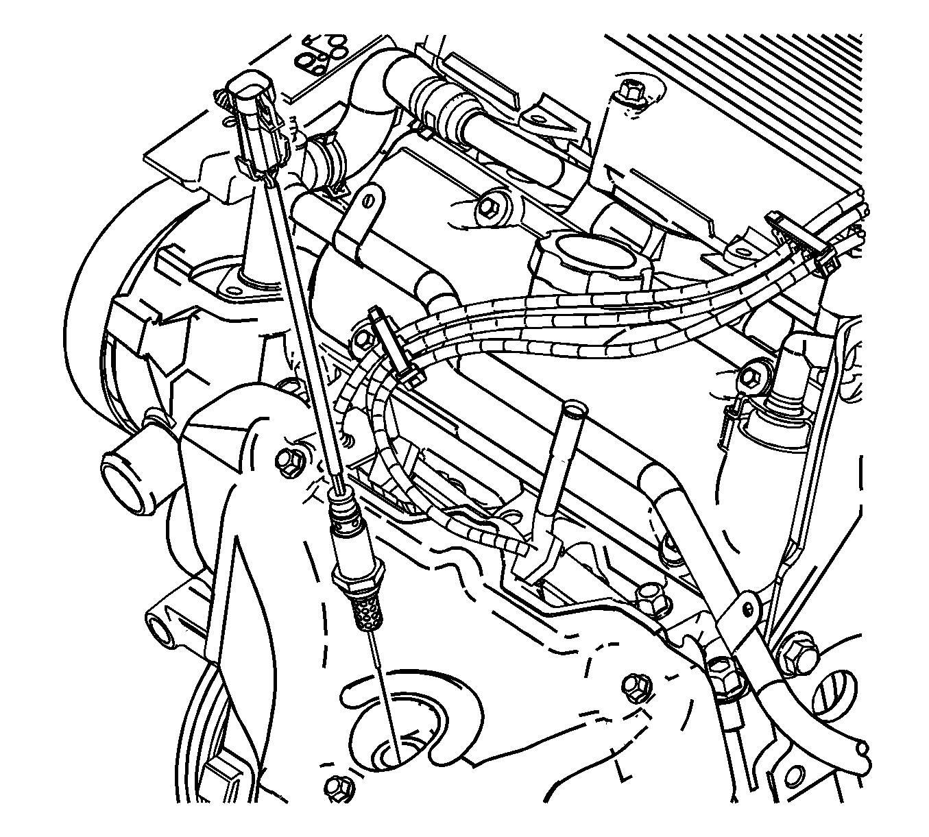
- Disconnect the front heated oxygen sensor (HO2S) from the connector at the side of the engine.
- Remove front HO2S using J 39194-B .
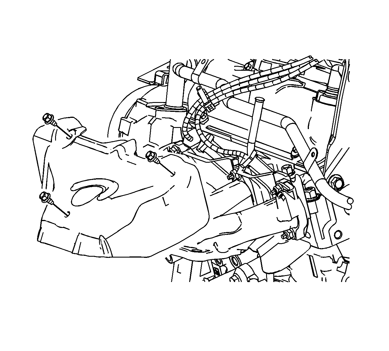
- Remove the exhaust manifold heat shield.
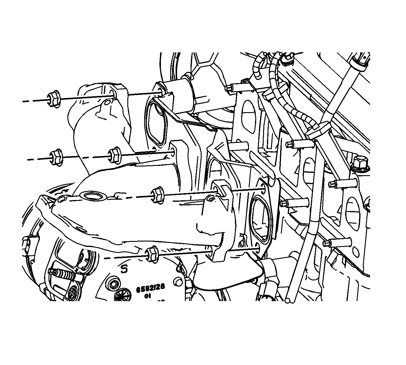
- Remove the upper exhaust manifold to cylinder head nuts.
- Raise the vehicle. Refer to Lifting and Jacking the Vehicle in General Information.
- Remove the crossover pipe. Refer to Exhaust Crossover Pipe Replacement .
- Remove the front catalyst assembly. Refer to Catalytic Converter Replacement .
- Remove the exhaust manifold nuts.
- Remove the exhaust manifold assembly.
- Remove the exhaust manifold gasket.


Installation Procedure
- Install a new manifold gasket on the cylinder head.
- Install the exhaust manifold.
- Install the exhaust manifold nuts.
- Install the front catalyst assembly and gasket. Refer to Catalytic Converter Replacement .
- Install the crossover pipe and gaskets. Refer to Exhaust Crossover Pipe Replacement .
- Install the exhaust manifold heat shield.
- Install the HO2S into the exhaust manifold using J 39194-B .
- Connect the HO2S electrical connector at the side of engine. Assure the connector is fully retained away from the exhaust manifold and heat shield edges.
- Install the air intake tube. Refer to Air Cleaner Inlet Duct Replacement in Engine Controls.

Notice: Refer to Fastener Notice in the Preface section.
Tighten
Tighten the exhaust manifold nuts to 16 N·m
(12 lb ft).

Tighten
Tighten the exhaust manifold heat shield bolts to
18 N·m (12 lb ft).

Important: Whenever the oxygen sensor is removed, coat the threads with nickel-based anti-seize compound, such as GM P/N 5613695, or equivalent.
Tighten
Tighten the oxygen sensor-to-exhaust manifold pipe
to 41 N·m (30 lb ft).
