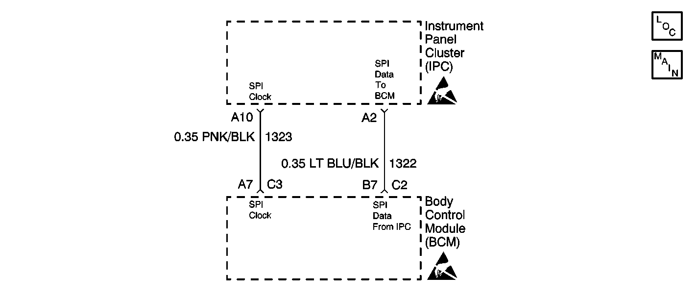
Circuit Description
The instrument panel cluster (IPC) and the body control module (BCM) share information by transmitting and receiving serial data. This is accomplished by using the three wire serial peripheral interface (SPI) method. The SPI data shared between the BCM and IPC is used to control the various indicators and gauges on the instrument cluster excluding the MIL, speedometer and tachometer. The SPI clock (CKT 1323) controls which module is communicating and works to keep the data pulses timed correctly. Circuit 1322 is used to transmit data from the cluster to the BCM. Circuit 1321 is used to transmit data from the BCM to the instrument cluster.
Conditions for Running the DTC
| • | Voltage supplied to the modules is in the normal operating range (approximately 9-16 volts). |
| • | The vehicle power mode (ignition switch position) requires serial data communication to occur. |
Conditions for Setting the DTC
The serial data from the IPC to the BCM is incorrect for 5 seconds.
Action Taken When the DTC Sets
The BCM uses a default value for the incorrect data received from the IPC.
Conditions for Clearing the DTC
| • | A current DTC U2001 will clear at the end of the current ignition cycle. |
| • | A history DTC U2001 will clear upon the receipt of a scan tool Clear DTCs command. |
| • | All the BCM history codes will be cleared after 100 ignition cycles (from OFF to ON) with no current codes active during the 100 ignition cycles. |
Diagnostic Aids
If the DTC is a history DTC, the problem may be intermittent. Perform the tests shown while wiggling the wiring and connectors. This may often cause the malfunction to appear.
Test Description
The number(s) below refer to the step number(s) on the diagnostic table.
Step | Action | Yes | No |
|---|---|---|---|
1 | Did you perform the Body Control System Diagnostic System Check? | Go to Step 2 | |
Does the scan tool display [normal state-XXX]? | Go to Testing for Intermittent Conditions and Poor Connections in Wiring Systems | Go to Step 3 | |
3 | Test the SPI Data circuit (1322) and the SPI clock circut (1323) for an open or short to ground. Refer to Circuit Testing and Wiring Repairs in Wiring Systems. Did you find and correct the condition? | Go to Step 7 | Go to Step 4 |
4 | Inspect for poor connections at the harness connector of the body control module. Refer to Testing for Intermittent Conditions and Poor Connections and Connector Repairs in Wiring Systems. Did you find and correct the condition? | Go to Step 7 | Go to Step 5 |
5 | Inspect for poor connections at the harness connector of the instrument cluster. Refer to Testing for Intermittent Conditions and Poor Connections and Connector Repairs in Wiring Systems. Did you find and correct the condition? | Go to Step 7 | Go to Step 6 |
6 | Replace the instrument cluster. Refer to Instrument Cluster Replacement in Instrument Panel, Gauges and Console. Did you complete the replacement? | Go to Step 7 | -- |
7 |
Does the DTC reset? | Go to Step 8 | System OK |
8 | Replace the body control module. Refer to Body Control Module Replacement . Important: Perform the set up procedure for the body control module. Refer to Body Control Module (BCM) Programming/RPO Configuration . Did you complete the replacement? | System OK | -- |
