Removal Procedure
- Relieve the fuel system pressure. Refer to Fuel Pressure Relief Procedure .
- Remove the quick-connect fittings at engine compartment fuel feed and return connecting pipes. Refer to Quick Connect Fitting(s) Service (Metal Collar) .
- Plug the fuel pipes.
- Raise the vehicle.
- Remove the quick-connect fittings at fuel sender and nylon fuel feed and return connecting pipes. Refer to Quick Connect Fitting(s) Service (Metal Collar) .
- Remove the exhaust heat shield.
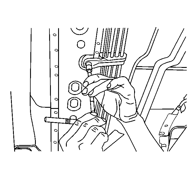
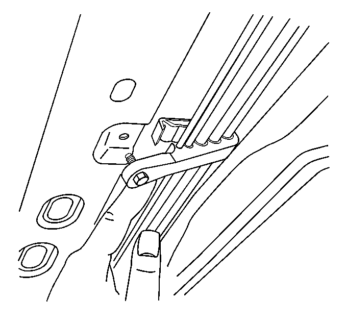
- Remove the fuel pipe mounting bolts from the body clips.
- Remove the fuel pipes from the body clips.
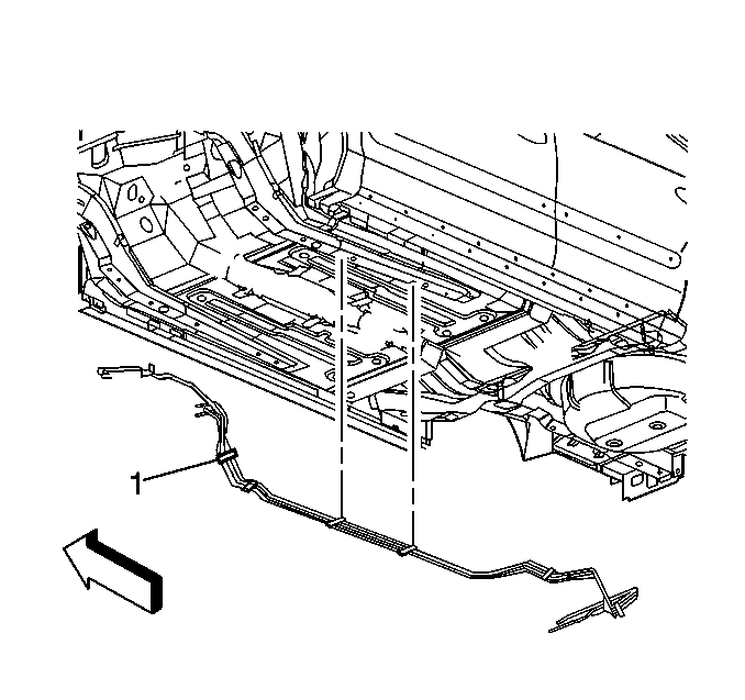
- Remove the fuel pipes (1) to be serviced.
Caution: To avoid any vehicle damage, serious personal injury or death when major components are removed from the vehicle and the vehicle is supported by a hoist, support the vehicle with jack stands at the opposite end from which the components are being removed and strap the vehicle to the hoist.

In the repairable areas, cut a piece of fuel hose 100 mm (4 in) longer than portion of the pipe removed. If more than a 152 mm (6 in) length of pipe is removed, use a combination of steel pipe and hose so that hose lengths will not be more than 254 mm (10 in), including hose overlap on fuel pipe.

Notice: If necessary, remove rust or burrs from the fuel pipes with an emery cloth. Use a radial motion with the fuel pipe end in order to prevent damage to the O-ring sealing surface. Use a clean shop towel in order to wipe off the male tube ends. Inspect all the connections for dirt and burrs. Clean or replace the components and assemblies as required.

Installation Procedure
- Install the fuel pipe and hose hardware (1).
- Position the fuel pipes in the body clips.
- Install the fuel pipe mounting bolts into the body clips.
- Install the exhaust heat shield.
- Remove the caps on the fuel pipes.
- Install the quick-connect fittings on the fuel pipes. Refer to Quick Connect Fitting(s) Service (Metal Collar) .
- Install the quick-connect fittings at engine compartment fuel feed and return pipes.
- Lower the vehicle.
- Install the negative battery cable.
- Inspect for fuel leaks through the following steps:

Notice: Use the correct fastener in the correct location. Replacement fasteners must be the correct part number for that application. Fasteners requiring replacement or fasteners requiring the use of thread locking compound or sealant are identified in the service procedure. Do not use paints, lubricants, or corrosion inhibitors on fasteners or fastener joint surfaces unless specified. These coatings affect fastener torque and joint clamping force and may damage the fastener. Use the correct tightening sequence and specifications when installing fasteners in order to avoid damage to parts and systems.


Notice: Use the correct fastener in the correct location. Replacement fasteners must be the correct part number for that application. Fasteners requiring replacement or fasteners requiring the use of thread locking compound or sealant are identified in the service procedure. Do not use paints, lubricants, or corrosion inhibitors on fasteners or fastener joint surfaces unless specified. These coatings affect fastener torque and joint clamping force and may damage the fastener. Use the correct tightening sequence and specifications when installing fasteners in order to avoid damage to parts and systems.
Tighten
Tighten the bolts to 6.0 N·m (53 lb in).
Tighten
| • | Tighten the exhaust shield bolt to 2.0 N·m (18 lb in). |
| • | Tighten the exhaust shield nuts to 1.0 N·m (9 lb in). |
| 10.1. | Turn the ignition switch to the ON position for two seconds. |
| 10.2. | Turn the ignition switch to the OFF position for ten seconds. |
| 10.3. | Turn the ignition switch to the ON position. |
| 10.4. | Check for fuel leaks. |
