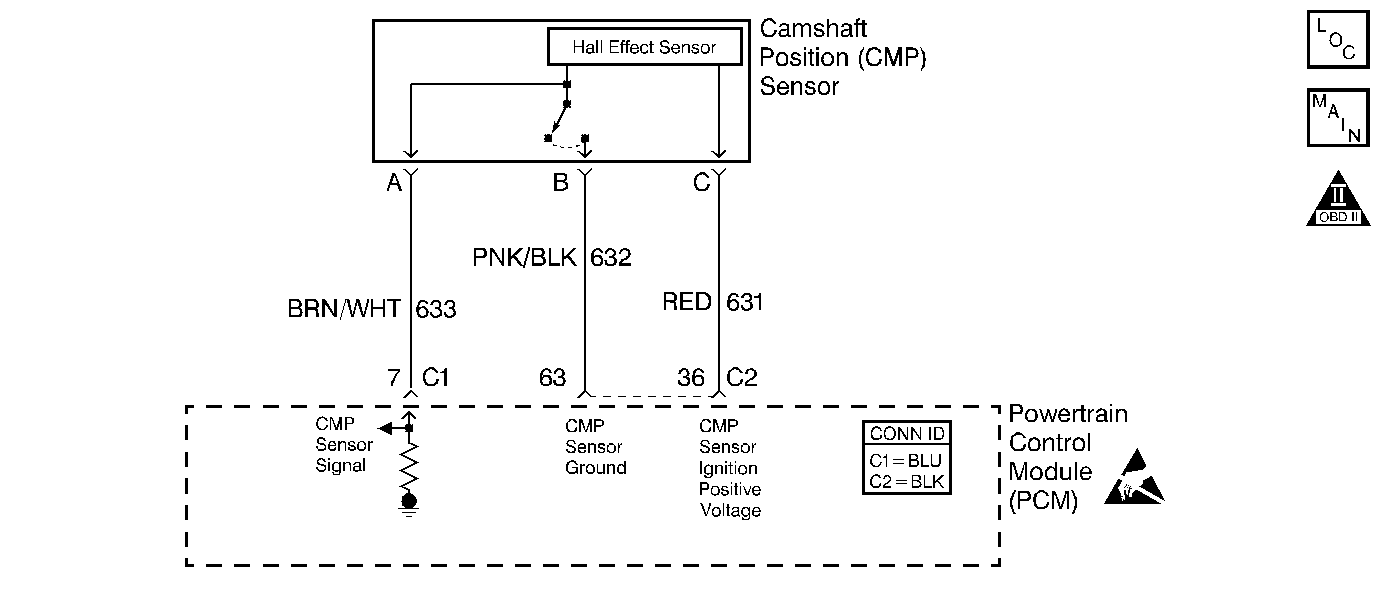
Circuit Description
The camshaft position (CMP) sensor correlates the crankshaft to camshaft position so that the Powertrain Control Module (PCM) can determine which cylinder is ready to be fueled by the injector. The CMP sensor also determines which cylinder is misfiring when a misfire is present. If the PCM receives an intermittent signal from the CMP, then the CMP Resync Counter will increment. When the PCM cannot use the information from the CMP sensor, a DTC is set and the PCM will fuel the engine by using the alternating synchronous double fire (ASDF) method.
Conditions for Running the DTC
The engine is running.
Conditions for Setting the DTC
The CMP Active Counter is not incrementing.
Action Taken When the DTC Sets
| • | The malfunction indicator lamp (MIL) illuminates. |
| • | The PCM records the operating conditions at the time when the diagnostic fails. This information stores in the Freeze Frame and Failure Records buffers. |
| • | A history DTC stores. |
| • | The coolant fan turns ON. |
Conditions for Clearing the MIL/DTC
| • | The MIL will turn OFF after three consecutive ignition cycles in which the diagnostic runs without a fault. |
| • | A history DTC will clear after 40 consecutive warm-up cycles without a fault. |
| • | The MIL/DTCs can be cleared by using the scan tool. |
Diagnostic Aids
| • | An Intermittent problem may be caused by the following conditions: |
| - | Poor electrical connection |
| - | Rubbed-through wire insulation |
| - | Broken wire inside the insulation |
| • | Thoroughly check any suspected circuitry for the following conditions: |
| - | Backed-out terminals |
| - | Improper mating |
| - | Broken locks |
| - | Improperly formed connectors |
| - | Damaged terminals |
| - | Poor terminal to wiring connections |
| - | Physical damage to the wiring harness |
Test Description
The number(s) below refer(s) to the step number(s) on the Diagnostic Table.
-
The Powertrain OBD System Check prompts you to complete some of the basic checks and to store the freeze frame and failure records data on the scan tool if applicable. This creates an electronic copy of the data captured when the malfunction occurred. The scan tool stores this data for later reference.
-
This step determines if the DTC P0342 is the result of a hard malfunction or an intermittent condition.
-
This step determines if the voltage is available to the CMP sensor through the PCM.
-
This step determines if the voltage is available to the CMP sensor through the PCM.
-
This step checks the output of the CMP sensor. If there is a varying voltage, then the problem is in the CMP signal circuit. If there is no varying voltage, then problem is in the CMP sensor electrical connections or is a malfunctioning CMP sensor.
-
Reprogram the replacement PCM and perform the crankshaft position system variation learn procedure. Refer to the latest Techline procedures for PCM reprogramming and the Crankshaft Position System Variation Learn for the crankshaft position system variation learn procedure.
Step | Action | Value(s) | Yes | No | ||||||
|---|---|---|---|---|---|---|---|---|---|---|
Did you perform the Powertrain On-Board Diagnostic (OBD) System Check? | -- | |||||||||
Is the CMP Active counter incrementing? | -- | |||||||||
3 |
Is the CMP Active Counter incrementing? | -- | ||||||||
Did the test light illuminate? | -- | |||||||||
Did the test light illuminate? | -- | |||||||||
6 |
Was a repair necessary? | -- | ||||||||
Does the DMM display a frequency reading that is varying between the specified value? | 0.5-2.6 Hz | |||||||||
8 |
Was a repair necessary? | -- | ||||||||
9 |
Does the test light illuminate? | -- | ||||||||
10 |
Does the test light illuminate? | -- | ||||||||
11 |
Was a repair necessary? | -- | ||||||||
12 |
Is the action complete? | -- | -- | |||||||
13 |
Is the action complete? | -- | -- | |||||||
14 |
Is the action complete? | -- | -- | |||||||
Is the action complete? | -- | -- | ||||||||
16 |
Does the scan tool indicate that this diagnostic has ran and passed? | -- | ||||||||
17 | Check to see if any additional DTCs are set. Does the scan tool display any DTCs that you have not diagnosed? | -- | Go to applicable DTC table | System OK |
