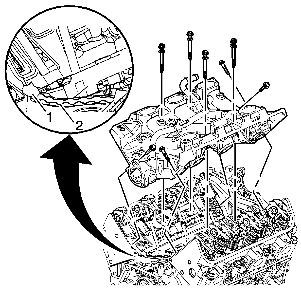
- Install the lower intake manifold gaskets.
- With gaskets in place apply a small drop 8-10 mm (0.31-0.39 in) of RTV sealer GM P/N 12346141 (Canadian P/N 10953433) or equivalent to the 4 corners of the intake manifold to block joint (1).
- Connect the 2 small drops with a bead of RTV sealer that is between 8-10 mm (0.31-0.39 in) wide and 3.0-5.0 mm (0.12-0.20 in) thick (2).
- Install the lower intake manifold.
- Tighten the lower intake manifold bolts in sequence to 7 N·m (62 lb in) on the first pass.
- Tighten the lower intake manifold center bolts in sequence to 13 N·m (115 lb in) on the final pass.
- Tighten the lower intake manifold diagonal bolt in sequence to 13 N·m (115 lb in) on the final pass.
- Tighten the lower intake manifold bolts in sequence to 7 N·m (62 lb in) on the first pass.
- Tighten the lower intake manifold bolts (1, 2, 3, 4) in sequence to 13 N·m (115 lb in) on the final pass.
- Tighten the lower intake manifold bolts (5, 6, 7, 8) in sequence to 25 N·m (18 lb ft) on the final pass.
- Install the lower intake manifold bolts.
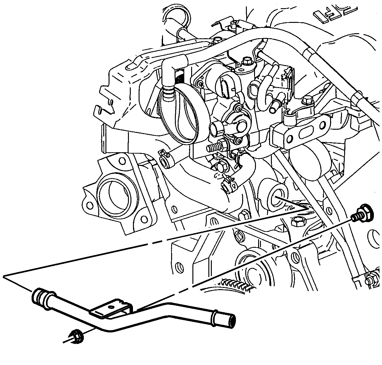
- Install the heater inlet pipe.
- Install the heater inlet pipe nut.
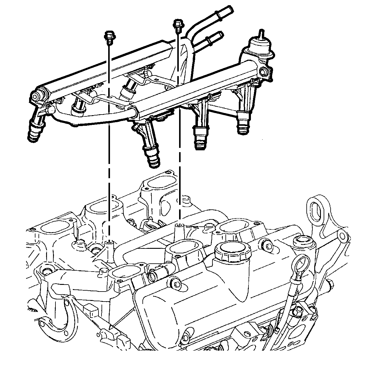
- Install the fuel injector rail assembly.
- Install the fuel injector rail bolts.
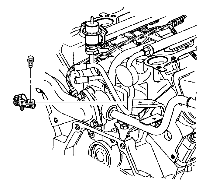
- Install the fuel feed and return pipe retaining clip.
- Install the fuel feed and return pipe retaining clip bolt.

Important: All gasket-mating surfaces need to be free of oil, and foreign material. Use GM P/N 12346139 (Canadian P/N 10953463) or equivalent to clean surfaces.

Notice: Maximum gasket performance is achieved when using new fasteners, which contain a thread-locking patch. If the fasteners are not replaced, a thread locking chemical must be applied to the fastener threads. Failure to replace the fasteners or apply a thread-locking chemical MAY reduce gasket sealing capability.
Important: All lower intake manifold bolts need to be cleaned, free of any foreign material, and reused only if new bolts are unavailable. Use GM P/N 12345382 (Canadian P/N 10953489) or equivalent and apply to the old intake manifold bolt threads.
Important: Manufacturer recommends the center bolts be fully torqued before the diagonal bolts to assure proper seal ability.
Important: Lower intake manifold bolts in location 6 and 7 should be torqued to specification using a crows foot type tool.
Notice: Use the correct fastener in the correct location. Replacement fasteners must be the correct part number for that application. Fasteners requiring replacement or fasteners requiring the use of thread locking compound or sealant are identified in the service procedure. Do not use paints, lubricants, or corrosion inhibitors on fasteners or fastener joint surfaces unless specified. These coatings affect fastener torque and joint clamping force and may damage the fastener. Use the correct tightening sequence and specifications when installing fasteners in order to avoid damage to parts and systems.
Important: The next three steps apply to the 3.1L engine only:
Tighten
Important: The next three steps apply to the 3.4L engine only:
Tighten

Tighten
Tighten the heater inlet pipe nut to 25 N·m (18 lb ft).

Important: Do not press on the fuel pressure regulator valve when installing the fuel injector rail assembly.
| 8.1. | Install the fuel injector O-rings using GM P/N 12345616, (Canadian P/N 993182) or equivalent. |
| 8.2. | Install the injector nozzles into the lower intake manifold injector bores. |
| 8.3. | Press on the injector rail using the palms of both hands until the injectors are fully seated. |
Tighten
Tighten the fuel injector rail bolts to 10 N·m (89 lb in).

Tighten
Tighten the fuel feed and return pipe retaining clip bolt to 8 N·m
(71 lb in).
