WHISTLE NOISE AT HIGHWAY SPEED AND/OR CERTAIN HTR. POSITION

SUBJECT: WHISTLE NOISE AT HIGHWAY SPEEDS AND/OR CERTAIN HEATER CONTROL POSITIONS (DIAGNOSIS PROCEDURE)
VEHICLES AFFECTED: 1990-91 U-VAN CHEVROLET LUMINA APV PONTIAC TRANS SPORT
THIS BULLETIN UPDATE RELEASES A NEW ANTENNA MAST FOR "DIAGNOSIS" - STEP 1, ALONG WITH WARRANTY INFORMATION. A SOURCE DISCLAIMER LISTED IN CORRECTION #1 WAS ALSO ADDED.
Some customers of 1990-91 U-Vans may comment about whistling sounds either while driving the vehicle at highway speeds and/or with the heater controls in certain positions.
CONDITIONS:
----------- 1. Constant whistle noise while driving at highway speeds or while driving with heater controls in any position EXCEPT MAX.
2. Whistle noises with the heater controls in the DEFROST OR MIX modes OR: with the control in the HEAT, MIX or DEFROST modes with the TEMP LEVER from 0 to 1/4 position and in 3/4 position (opposite the MIX button).
CAUSES:
------- 1. Speed related noises are most likely due to high velocity air passing through the cowl panel grill, that may be mispositioned.
2. Noises with the heater controls in certain positions may be due to EITHER air leakage past the hinge area of the defroster door OR: air passing through the narrow opening between the temperature door baffle and the outside edge of the slave door.
DIAGNOSIS:
---------- May be performed by road testing the vehicle and having a 10 mm wrench in your possession OR by testing the Heater and A/C system with the controls set in positions as noted in the condition sections above.
1. Road test the vehicle at speeds between 50 - 88 KPH (30 and 55 MPH). Note any noises present and pull off the road into a safe parking area. Using the 10mm wrench, remove the antenna mast, retest the vehicle as before and note any change in noise.
- If the noise changed and no whistle noise is heard, the condition is antenna related. Replace the antenna mast with P/N 10220990.
- If the noise DID NOT CHANGE, perform Correction #1 only.
For vehicles repaired under warranty use:
Labor Operation: R-0220 Labor Time: 0.2 Hour.
2. Whistle noises with controls in certain positions may be diagnosed by parking the vehicle in a QUIET area and noting noises while the controls are positioned as indicated in the condition sections above.
- For noises noted with controls in DEFROST or MIX or DEFROST modes and TEMP LEVER from 0 to 1/4 position and 3/4 position perform Correction #3.
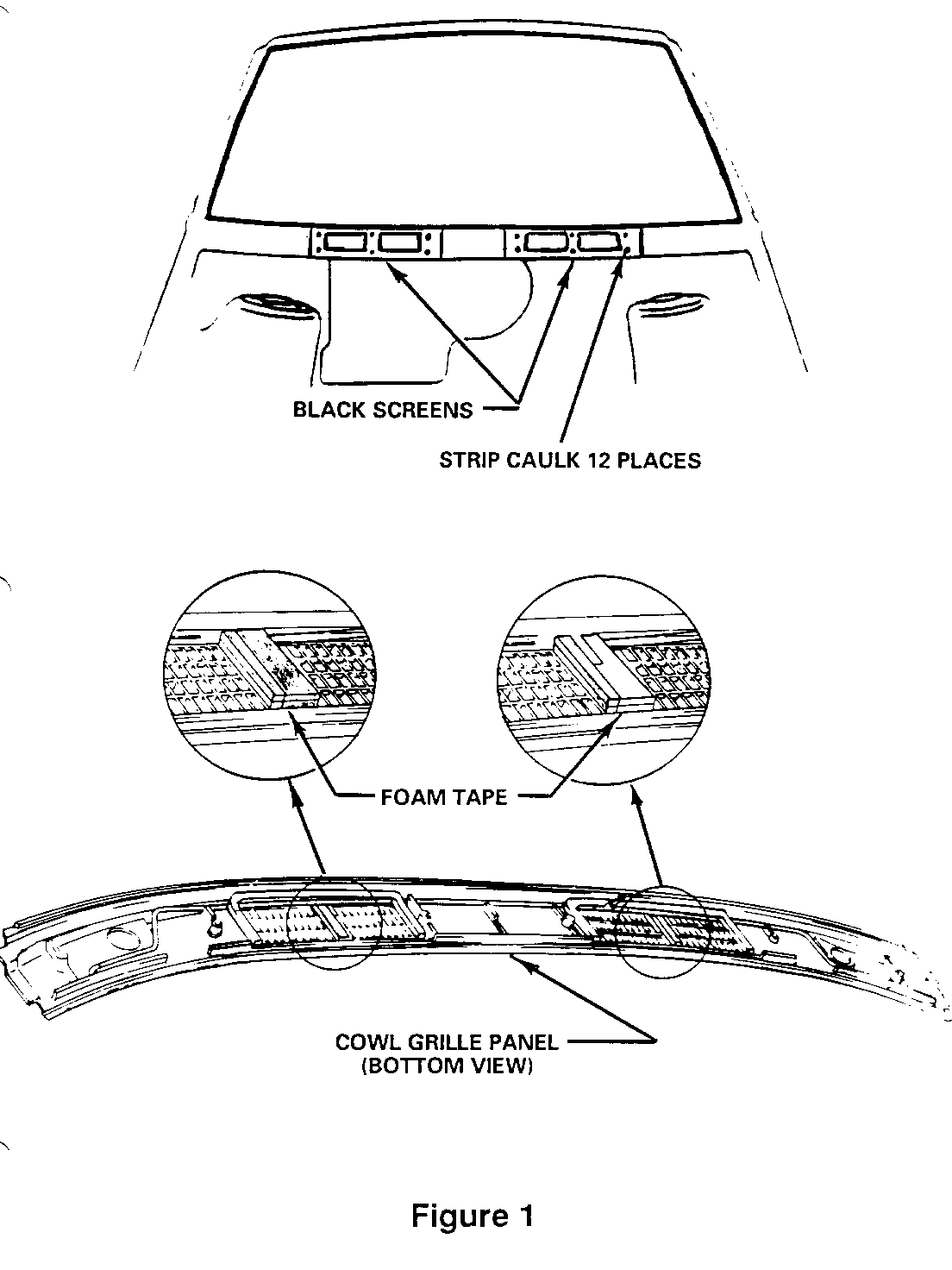
CORRECTION: #1. Noises From The Cowl Panel Area, Refer To Figure 1. ---------------------------------------------------
Parts required: - 2 Pcs. of black house screening, 10cm x 38cm (4", x 15") --------------- (obtain locally) - 6 Pcs. of foam tape, *3M# 06370, 19mm x 6mm x 64mm (3/4" x 1/4" x 2 1/2") long.
or Optional - 4 Pcs. of *American/Dominion # RAB1, 25mm x 6mm x 64mm (1" x 1/4" x 2 1/2") long (or equivalent).
*We believe these sources and their equipment to be reliable. There may be additional manufacturers of such equipment. General Motors does not endorse, indicate any preference for or assume any responsibility for the products or equipment from these firms or for any such items which may be available from other sources.
1. Remove cowl panel from vehicle by:
- removing antenna mast. - positioning wipers halfway up on windshield and remove the wiper arm as specified in Section 8E of the Service Manual. - removing the 6 attaching screws. - disconnecting the washer hose.
2. Carefully remove any excess urethane squeeze out from bottom edge of windshield using a utility or razor knife.
3. Install the 2 pieces of screen over the cowl openings and retain in place using small amounts of strip caulk (3M# 08578 or equivalent) placed in each corner under the screen as shown in Figure 1.
4. Cut a small slit in the driver's side screen to permit an opening for the washer hose, check the cowl panel for the location.
5. Install double thickness of foam to the centre areas of the cowl grill openings. It will be necessary to trim the foam tape for the LH side of the cowl grill area to clear the washer hose retainer clip. If the 19mm (3/4 inch) wide foam tape is used it will be necessary to cut 6mm (1/4") strips to fill in the centre grill areas.
6. Reattach the washer hose to the panel and place the panel into the body opening.
7. Position the panel CENTRE AND REARWARD in the opening and, using the panel as a template, if necessary, to CAREFULLY REDRILL THE ATTACHING HOLES using a drill motor and 1/8" diameter drill bit.
NOTICE: CARE MUST BE TAKEN WHEN DRILLING TO AVOID MARRING THE COWL PANEL.
8. Reinstall the attaching screws and antenna mast.
9. Prior to installing the wiper arms, return the wiper motor to the park position, and install the arms as specified in Section 8E of the Service Manual.
For vehicles repaired under warranty use:
Labor Time: 0.8 Hour.
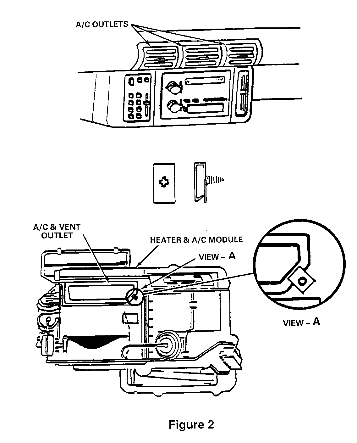
CORRECTION: #2. Heater System Noises In DEFROST Or MIX, Refer To Figure 2 --------------------------------------------------------- Parts required: GM P/N 20418416 Stop, air inlet valve (plastic clip) --------------- 1. Remove the centre and right hand A/C and vent outlets.
2. Fabricate a special tool, 46cm (18") long, from socket extensions and a deep well 7mm socket. Tape the joints of the extensions and socket securely.
3. Insert the pointed end of the clip FIRMLY, BUT NOT TOO TIGHT, into the socket.
4. With the clip in the socket, insert the tool through the centre opening and push the A/C vent door open slightly.
5. Position the clip onto the edge of the door opening, as shown in View A, and remove the tool from the clip and outlet.
6. Reinstall the A/C and vent outlets.
For vehicles repaired under warranty use:
Labor Time: 0.2 Hour.
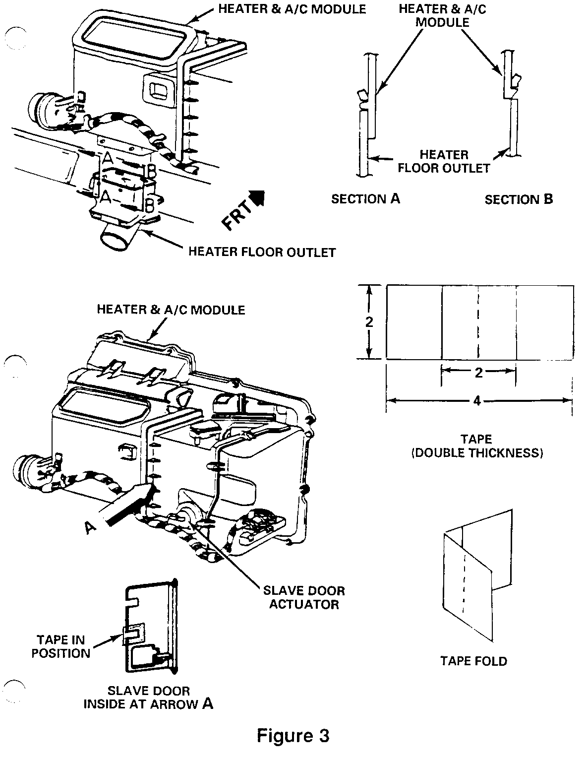
CORRECTION # 3 Heater System Noises In HEAT, MIX Or DEFROST Modes With Temp Lever In From 0 - 1/4 Position And 3/4 Position, Refer To Figure 3. --------------------------------------------------------------
Parts Required: 4 Pcs. of 3M# 06930 Auto Body Repair Tape (or equivalent) --------------- IMPORTANT: For vehicles without rear Air Distribution use only Steps 1, 2, 10 thru 16 AND 24.
1. Place heater controls in HEAT mode.
2. Remove the left hand sound insulator.
3. Remove driver's seat.
4. Remove left hand sill plate.
5. Remove left hand cowl side panel.
6. Remove second row seating (Section 10 in Service Manual).
7. Remove the two front LH second row seat anchor plates.
8. Raise and pull back the carpeting to expose the floor ducts.
9. Remove the support screws holding the floor ducts in position and slide the floor ducts rearward to clear the heater floor outlet.
10. Remove the heater floor outlet by pushing in on the front of the module to clear the tangs, shown in Section B of Figure 3 and pull rearward and down to clear the projections shown in Section A of Figure 3.
11. Cut 4 pcs. of 3M# 06930 tape, 2 pcs. 51mm (2 inches) long and 2 pcs. 102mm (4 inches) long. Locate and fold the pieces of tape, as shown in Figure 3, with the adhesive side of the tape pieces in the same direction.
12. Remove the vacuum hose from the slave door vacuum actuator and attach a hand operated vacuum pump to the actuator.
13. With your left hand up inside the heater outlet opening apply enough vacuum with the pump to open the slave door to the mid position. Using your left hand-locate the slave door and the two slots in the edge of the door.
14. When the slots are located, obtain the two previously folded pieces of tape and apply them to the slave door to cover the two slots, as shown in Figure 3. Press tape firmly to both sides of the slave door.
15. Remove vacuum pump and install the vacuum hose to the actuator.
16. Install the heater floor outlet.
IMPORTANT: If the module attachments for the floor outlet were damaged during removal, you can drill two 1/8" diameter holes in area of the projections shown in Section A of Figure 3 and use P/N 10133068 screws for the attachment of the floor outlet.
17. Slide floor ducts back into position and install the screws.
18. Install carpeting.
19. Install the two second seat anchor plates.
20. Install second row seats.
21. Install left hand cowl side panel.
22. Install left hand sill plate.
23. Install driver's seat.
24. Install left hand sound insulator.
For vehicles repaired under warranty use:
Labor Time: 0.4 Hr. - Without Rear Air Distribution 1.0 Hr. - With Rear Air Distribution


General Motors bulletins are intended for use by professional technicians, not a "do-it-yourselfer". They are written to inform those technicians of conditions that may occur on some vehicles, or to provide information that could assist in the proper service of a vehicle. Properly trained technicians have the equipment, tools, safety instructions and know-how to do a job properly and safely. If a condition is described, do not assume that the bulletin applies to your vehicle, or that your vehicle will have that condition. See a General Motors dealer servicing your brand of General Motors vehicle for information on whether your vehicle may benefit from the information.
