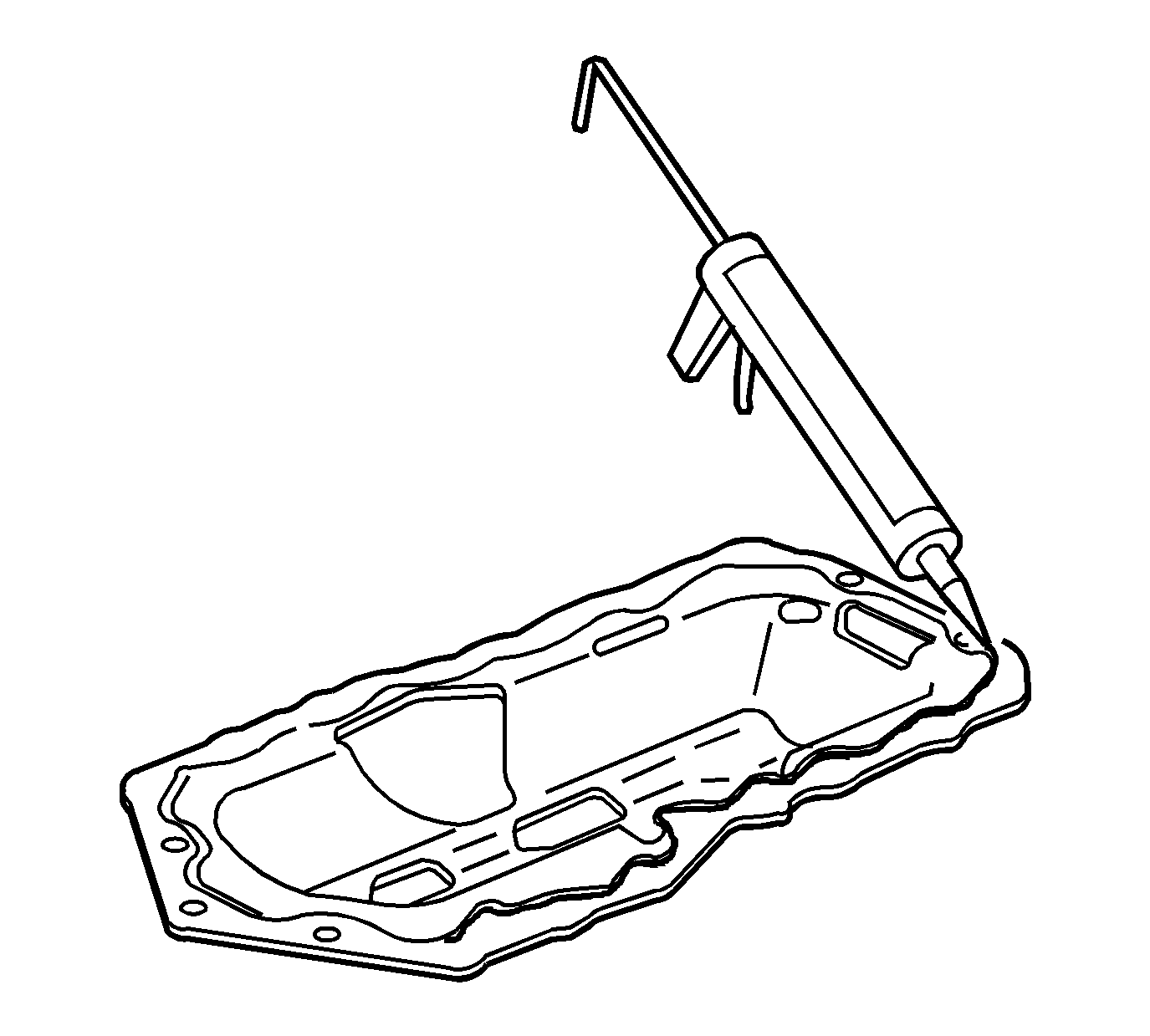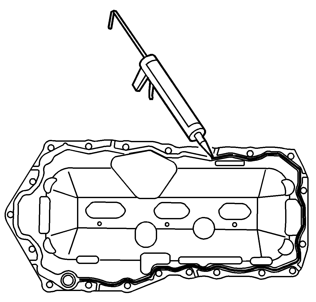
- Apply a continuous bead 6.35 mm (0.25 in) thick of RTV sealer GM P/N 12378521 (Canadian P/N 88901148) to the topside of the new gasket. Apply the RTV sealant directly over the gaskets
sealing bead.
- Install the NEW oil pan gasket onto the engine.

- Apply a continuous bead 6.35 mm (0.25 in) thick of RTV sealer GM P/N 12378521 (Canadian P/N 88901148) to the bottom side of the new gasket. Apply the RTV sealant directly over the gaskets
sealing bead.
Notice: Install the oil level sensor, located in the oil pan, after the oil
pan is installed. The sensor may be damaged if the oil level sensor is installed
first.
Notice: Use the correct fastener in the correct location. Replacement fasteners
must be the correct part number for that application. Fasteners requiring
replacement or fasteners requiring the use of thread locking compound or sealant
are identified in the service procedure. Do not use paints, lubricants, or
corrosion inhibitors on fasteners or fastener joint surfaces unless specified.
These coatings affect fastener torque and joint clamping force and may damage
the fastener. Use the correct tightening sequence and specifications when
installing fasteners in order to avoid damage to parts and systems.

- Install the oil pan gasket and the oil pump pipe and screen assembly.
Tighten
Tighten the oil pump screen bolts to 15 N·m (11 lb ft).

- Install the oil pan.
- Clean the oil pan bolts and apply one drop of thread lock compound GM P/N 12345382 or equivalent to the oil pan bolt threads.
Important: Do not overtighten bolts or damage to the oil pan may occur, resulting in an oil leak.
- Install the oil pan bolts.
Tighten
Tighten the oil pan bolts to 14 N·m (125 lb in).
- Install the engine mount and the engine mount bracket. Install the engine mount bracket bolts to the engine. Refer to
Engine Mount Bracket Replacement.
- Install new right side frame bolts. Make sure the frame is suitably supported. Install new left side frame bolts. Refer to
Frame Removal.
- Lower the vehicle.
- Use the
J 28467-B
in order to lower the engine.
- Raise and suitably support the vehicle. Refer to
Lifting and Jacking the Vehicle.
- Install the lower engine mount nuts. Refer to
Engine Mount Strut Replacement.

- Install the oil level sensor.
Tighten
Tighten the oil level sensor to 20 N·m (15 lb ft).
- Connect the oil level sensor wiring harness connector.
- Install the torque converter cover. Refer to
Torque Converter Cover Replacement for the 4T65-E transaxle.
- Connect the power steering oil cooler pipe brackets to the frame.

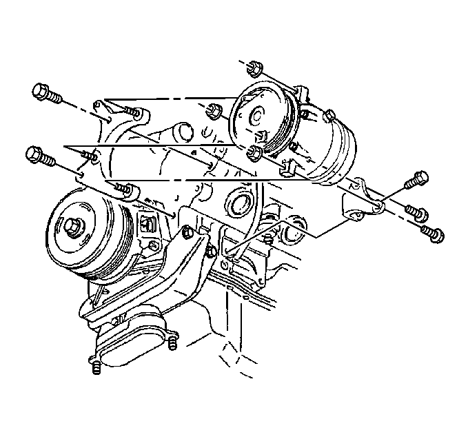
- Install the AC compressor bracket bolts. Refer to
Air Conditioning Compressor Replacement.

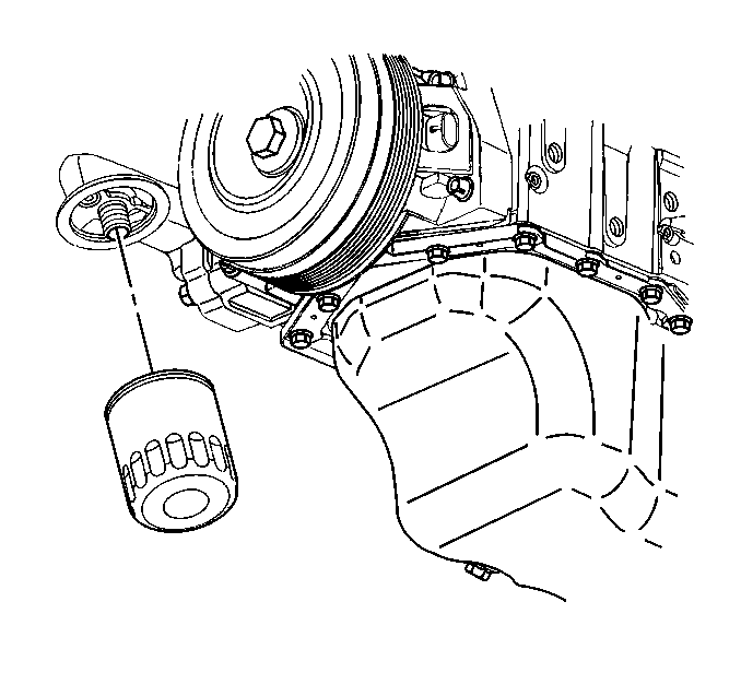
- Install the new oil filter. Refer to
Engine Oil and Oil Filter Replacement.
- Install the oil pan bolt. Refer to
Engine Oil and Oil Filter Replacement.
- Install the right engine splash shield. Refer to
Engine Splash Shield Replacement.
- Install the right front tire and wheel. Refer to
Tire and Wheel Removal and Installation.
- Connect the catalytic converter pipe to the right exhaust manifold. Refer to
Catalytic Converter Replacement.
- Lower the vehicle.
- Remove the
J 36462-A
, the
J 28467-B
, and the
J 28467-90A
.
- Install the drive belt. Refer to
Drive Belt Replacement.
- Install the engine mount struts to the engine. Refer to
Engine Mount Strut Replacement and
Engine Mount Strut Replacement.
- Carefully install the throttle body air inlet duct.
- Fill the crankcase with new engine oil. Refer to
Engine Oil and Oil Filter Replacement.
- Connect the negative battery cable. Refer to
Battery Negative Cable Disconnection and Connection.
- Inspect for the proper fluid levels.
- Inspect for leaks.
- Measure the wheel alignment. Refer to
Wheel Alignment Specifications.


