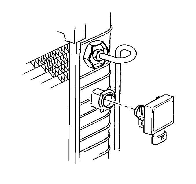
For 1990-2009 cars only
Removal Procedure
- Disconnect the battery ground (negative) cable. Refer to Battery Negative Cable Disconnection and Connection .
- Partially drain the radiator. Refer to Cooling System Draining and Filling .
- Disconnect the electrical connector from the low coolant module.
- Remove the low coolant module.
- Check the condition of the O-ring seal.

Caution: Before servicing any electrical component, the ignition and start switch must be in the OFF or LOCK position and all electrical loads must be OFF, unless instructed otherwise in these procedures. If a tool or equipment could easily come in contact with a live exposed electrical terminal, also disconnect the negative battery cable. Failure to follow these precautions may cause personal injury and/or damage to the vehicle or its components.
Important: To unlock the low coolant module, lift one leg of the snap clip from its locked position and pull outward with a slight twisting motion.
Installation Procedure
- Install the O-ring. Lubricate the O-ring seal with coolant.
- Place the snap clip leg in place.
- Install the low coolant module.
- Connect the electrical connector to the low coolant module.
- Connect the battery ground (negative) cable. Refer to Battery Negative Cable Disconnection and Connection .
- Fill the radiator. Refer to Cooling System Draining and Filling .
- Inspect for leaks.

