SERVICE MANUAL UPDATE-SEC. 10 FRONT SEATS - POLICE VEHICLES

SUBJECT: SECTION 10 - FRONT SEATS
VEHICLES AFFECTED: 1993 "W" MODEL (POLICE VEHICLE)
1993 Chevrolet Lumina police vehicles are equipped with Recaro front seats. Whenever servicing these seats, refer to the service procedures listed below.
FRONT SEAT ASSEMBLY:
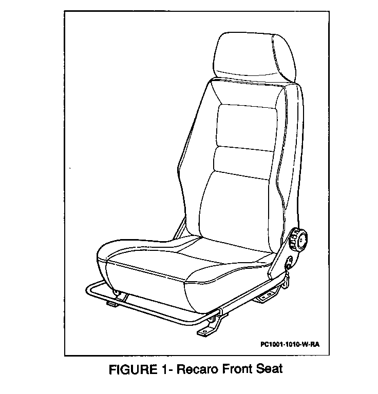
Figure 1
Remove or Disconnect
1. Operate seat to full-rearward position.
2. Front anchor bolts/screws.
3. Operate seat to full-forward position.
4. Rear anchor bolts/screws.
5. Seat assembly ensuring spacer washers remain in place.
Install or Connect
1. Seat assembly ensuring spacer washers are located between floor pan and seat track.
2. Rear anchor bolts/screws.
Tighten
o Bolts/screws to 24 N.m (18 lb.ft.).
3. Operate seat to full-rearward position.
4. Front anchor bolts/screws.
Tighten
o Bolts/screws to 24 N.m (18 lb.ft.).
FRONT SEATBACK ASSEMBLY:
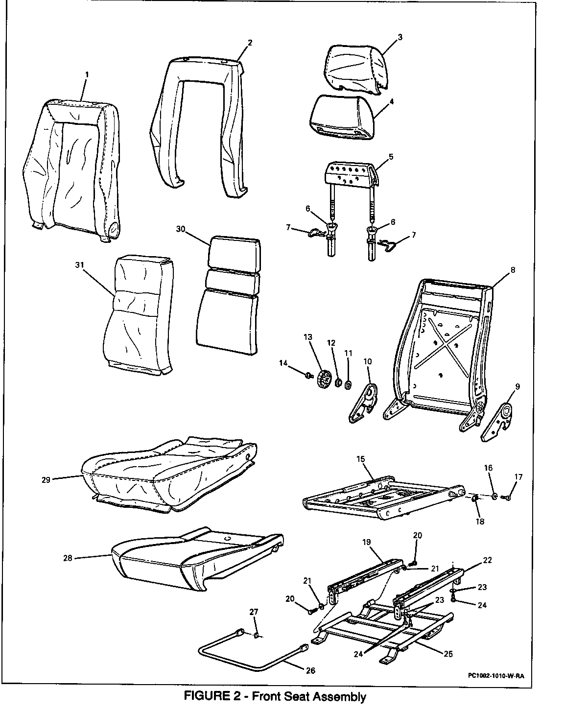
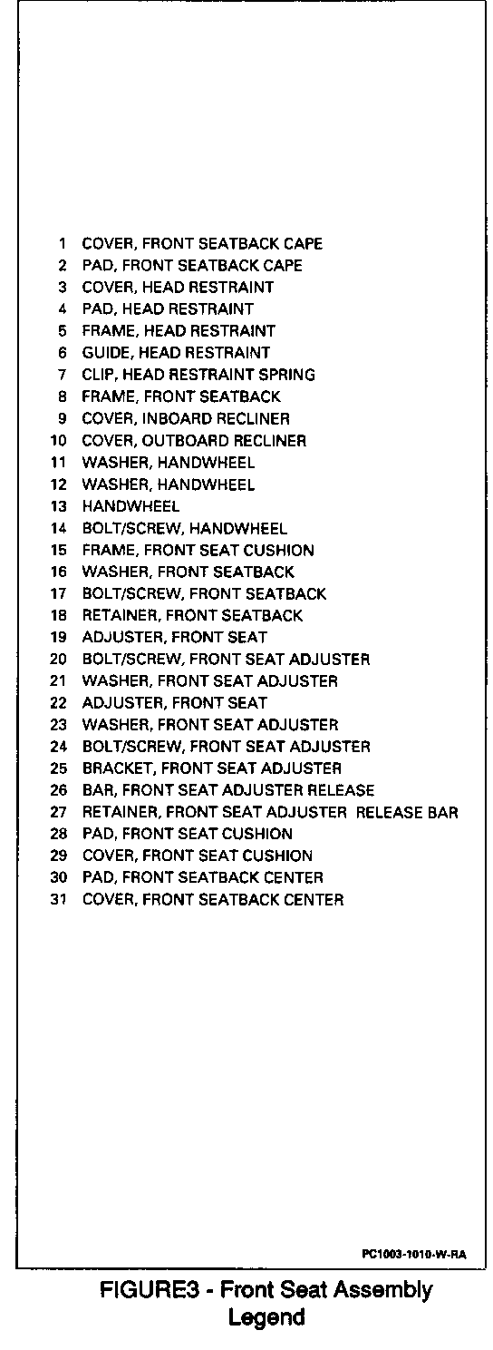
Figures 2 and 3
Remove or Disconnect
1. Recliner trim covers. Refer to "Front Seat Trim and Covers" in this bulletin.
2. Seatback to seat cushion frame retainers from pins.
3. Seatback to seat cushion frame bolts/screws and washers.
4. Seatback from pins.
Install or Connect
1. Seatback to pins.
2. Seatback to seat cushion frame bolts/screws and washers.
Tighten
o Bolts/screws to 11 N.m (97 lb.in.)
3. Seatback to seat cushion frame retainers to pins.
4. Recliner trim covers. Refer to "Front Seat Trim and Covers" in this bulletin.
FRONT SEAT CUSHION ASSEMBLY:
Figures 2 and 3
Remove or Disconnect
1. Seat assembly. Refer to "Front Seat Assembly" in this bulletin.
2. Seatback. Refer to "Front Seat Assembly" in this bulletin.
3. Seat adjuster assembly from front seat cushion assembly. Refer to "Front Seat Adjuster Assembly" in this bulletin
Install or Connect
1. Front seat cushion assembly to seat adjuster assembly. Refer to "Front Seat Adjuster Assembly" in this bulletin.
2. Seatback. Refer to "Front Seatback Assembly" in this bulletin.
3. Seat assembly. Refer to "Front Seat Assembly" in this bulletin.
FRONT SEATBACK CENTRE CUSHION:
Figures 2 and 3
Remove or Disconnect
1. Front seatback assembly. Refer to "Front Seatback Assembly" in this bulletin.
2. Head restraint. Refer to "Head Restraint" in this bulletin.
3. J-retainer on bottom of front seatback centre cushion.
4. Trim retainer rings connecting front seatback centre cushion to seatback frame.
5. Front seatback centre cushion swing wire from under tabs on seatback frame. Bend tabs as necessary to release swing wire.
6. Front seatback centre cushion from frame.
Install or Connect
1. Front seatback centre cushion to seatback frame.
2. Front seatback centre cushion swing wire under tabs on seatback frame. Bend tabs as necessary to secure swing wire.
3. Trim retainer rings connecting front seatback centre cushion to seatback frame.
4. J-retainer on bottom of front seatback centre cushion.
5. Head restraint. Refer to "Head Restraint" in this bulletin.
6. Front seatback assembly. Refer to "Front Seatback Assembly" in this bulletin.
FRONT SEATBACK CAPE CUSHION:
Figures 2 and 3
Remove or Disconnect
1. Front seatback centre cushion. Refer to "Front Seatback Centre Cushion" in this bulletin.
2. Front seatback cape cushion swing wires from under tabs on seatback frame. Bend tabs as necessary to release swing wires.
3. Front seatback cape cushion from seatback frame.
Install or Connect
1. Front seatback cape cushion to seatback frame.
2. Front seatback cape cushion swing wires under tabs on seatback frame. Send tabs as necessary to secure swing wires.
3. Front seatback centre cushion. Refer to "Front Seatback Centre Cushion" in this bulletin.
FRONT SEAT CUSHION:
Figures 2 and 3
Remove or Disconnect
1. Front seat cushion assembly. Refer to "Front Seat Cushion Assembly" in this bulletin,
2. J-retainers.
3. Front seat cushion assembly swing wires from under tabs on seat cushion frame. Send tabs as necessary to release swing wires.
4. Front seat cushion from seat cushion frame.
Install or Connect
1. Front seat cushion to seat cushion frame.
2. Front seat cushion assembly swing wires under tabs on seat cushion frame. Bend tabs as necessary to secure swing wires.
3. J-retainers.
4. Front seat cushion assembly. Refer to "Front Seat Cushion Assembly" in this bulletin.
FRONT SEAT TRIM AND COVERS:
RECLINER TRIM COVER - OUTBOARD
Figures 2 and 3
Remove or Disconnect
1. Handwheel. Refer to "Handwheel" in this bulletin.
2. Three pins. Push out from inside of cover.
3. Recliner trim cover.
Install or Connect
1. Recliner trim cover.
2. Three pins.. Install from outboard side of cover using a rubber mallet.
3. Handwheel. Refer to "Handwheel" in this bulletin.
RECLINER TRIM COVER - INBOARD
Figures 2 and 3
Remove or Disconnect
1. Three pins.. Push out from inside of cover.
2. Recliner trim cover.
Install or Connect
1. Recliner trim cover.
2. Three pins.. Install from outboard side of cover using a rubber mallet.
FRONT SEATBACK CENTRE COVER OR PAD
Figures 2 and 3
Remove or Disconnect
1. Front seatback centre cushion. Refer to "Front Seatback Centre Cushion" in this bulletin.
2. Trim retainer rings from front seatback centre cushion.
3. Swing wires.
4. Staples.
5. Front seatback centre cover from foam pad.
Install or Connect
1. Front seatback centre cover to foam pad.
2. Staples.
3. Swing wires.
4. Trim retainer rings to front seatback centre cushion.
5. Front seatback centre cushion. Refer to "Front Seatback Centre Cushion" in this bulletin.
FRONT SEATBACK CAPE COVER OR PAD
Figure 2 and 3
Remove or Disconnect
1. Front seatback cape cushion. Refer to "Front Seatback Cape Cushion" in this bulletin.
2. J-retainers.
3. Front seatback cape cover from foam pad.
Install or Connect
1. Front seatback cape cover to foam pad.
2. J-retainers.
3. Front seatback cape cushion. Refer to "Front Seatback Cape Cushion" in this bulletin.
FRONT SEAT CUSHION COVER OR PAD
Figures 2 and 3
Remove or Disconnect
1. Front seat cushion. Refer to "Front Seat Cushion: in this bulletin.
2. Trim retainer rings from front seat cushion assembly.
3. Swing wires.
4. Front seat cushion cover from foam pad.
Install or Connect
1. Front seat cushion cover to foam pad.
2. Swing wires.
3. Trim retainer rings to front seat cushion assembly.
4. Front seat cushion. Refer to "Front Seat Cushion" in this bulletin.
HEAD RESTRAINT COVER:
Figures 2 and 3
Remove or Disconnect
1. Raise head restraint.
2. J-retainers.
3. Head restraint cover from foam pad.
Install or Connect
1. Head restraint cover to foam pad.
2. J-retainers.
3. Lower head restraint.
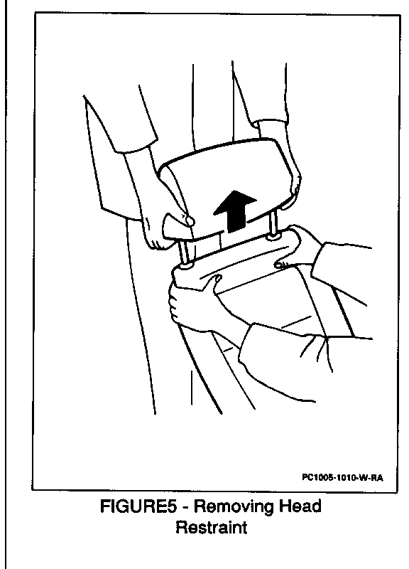
HEAD RESTRAINT:
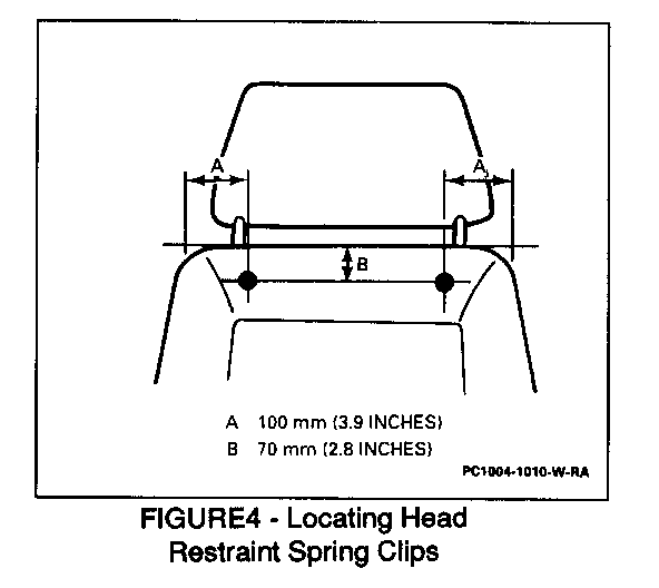
Figures 4 and 5
Remove or Disconnect
1. Fully lower head restraint.
2. Locate head restraint ratchet springs in upper portion of seatback.
3. Press and hold both head restraint ratchet springs with thumbs.
4. Head restraint with quick upward motion while holding ratchet springs.
Install or Connect
1. Head restraint posts into seatback openings.
2. Fully lower head restraint.
HANDWHEEL:
--------- Figures 2 and 3
Remove or Disconnect
1. Bolt/screw.
2. Handwheel and washers.
Install or Connect
1. Handwheel and washers.
2. Bolt/screw.
Tighten
o Bolt/screw to 5.4 N.m (48 lb.in.).
FRONT SEAT ADJUSTER ASSEMBLY:
Figures 2 and 3
Remove or Disconnect
1. Front seat assembly. Refer to "Front Seat Assembly" in this bulletin.
2. Bolts/screws from seat cushion assembly.
3. Front seat adjuster assembly from seat cushion assembly.
Install or Connect
1. Front seat adjuster assembly to seat cushion assembly.
2. Bolts/screws to seat cushion assembly.
Tighten
o Bolts/screws to 1 N.m (97 lb.in.).
3. Front seat assembly. Refer to "Front Seat Assembly" in this bulletin.
FRONT SEAT RECLINER ASSEMBLY:
Other than the recliner handwheel, the front seat recliner assembly is not serviceable.
FRONT SEAT ADJUSTER:
Figures 2 and 3
Remove or Disconnect
1. Front seat adjuster assembly. Refer to "Front Seat Adjuster Assembly" in this bulletin.
2. Front seat adjuster release bar. Refer to "Front Seat Adjuster Release Bar" in this bulletin.
3. Bolts/screws and washers from bracket.
4. Front seat adjuster from bracket.
Install or Connect
1. Front seat adjuster to bracket.
2. Bolts/screws and washers to bracket. Tighten. Bolts/screws to 23 N.m (17 lb.ft.).
3. Front seat adjuster release bar. Refer to "Front Seat Adjuster Release Bar" in this bulletin.
4. Front seat adjuster assembly. Refer to "Front Seat Adjuster Assembly" in this bulletin.
FRONT SEAT ADJUSTER RELEASE BAR:
Figures 2 and 3
Remove or Disconnect
1. Retainers using a screwdriver to pry retainers off.
2. Front seat adjuster release bar from adjusters.
Install or Connect
1. Front seat adjuster release bar to adjusters.
2. Retainers by pressing into position.
General Motors bulletins are intended for use by professional technicians, not a "do-it-yourselfer". They are written to inform those technicians of conditions that may occur on some vehicles, or to provide information that could assist in the proper service of a vehicle. Properly trained technicians have the equipment, tools, safety instructions and know-how to do a job properly and safely. If a condition is described, do not assume that the bulletin applies to your vehicle, or that your vehicle will have that condition. See a General Motors dealer servicing your brand of General Motors vehicle for information on whether your vehicle may benefit from the information.
