For 1990-2009 cars only
Special Tools
| • | J-2619-A Slide Hammer w/Adapter |
| • | J 3289-20 Holding Fixture |
| • | J 8614-01 Flange and Pulley Holding Tool |
| • | J 29369-2 Bushing and Bearing Remover |
| • | J 44737 Shift Rail Bearing Remover |
| • | J 44738 Bearing Remover |
| • | J 45358 Case Spreader |
| • | J 45759 Assembly Fixture |
For equivalent regional tools, refer to Special Tools.
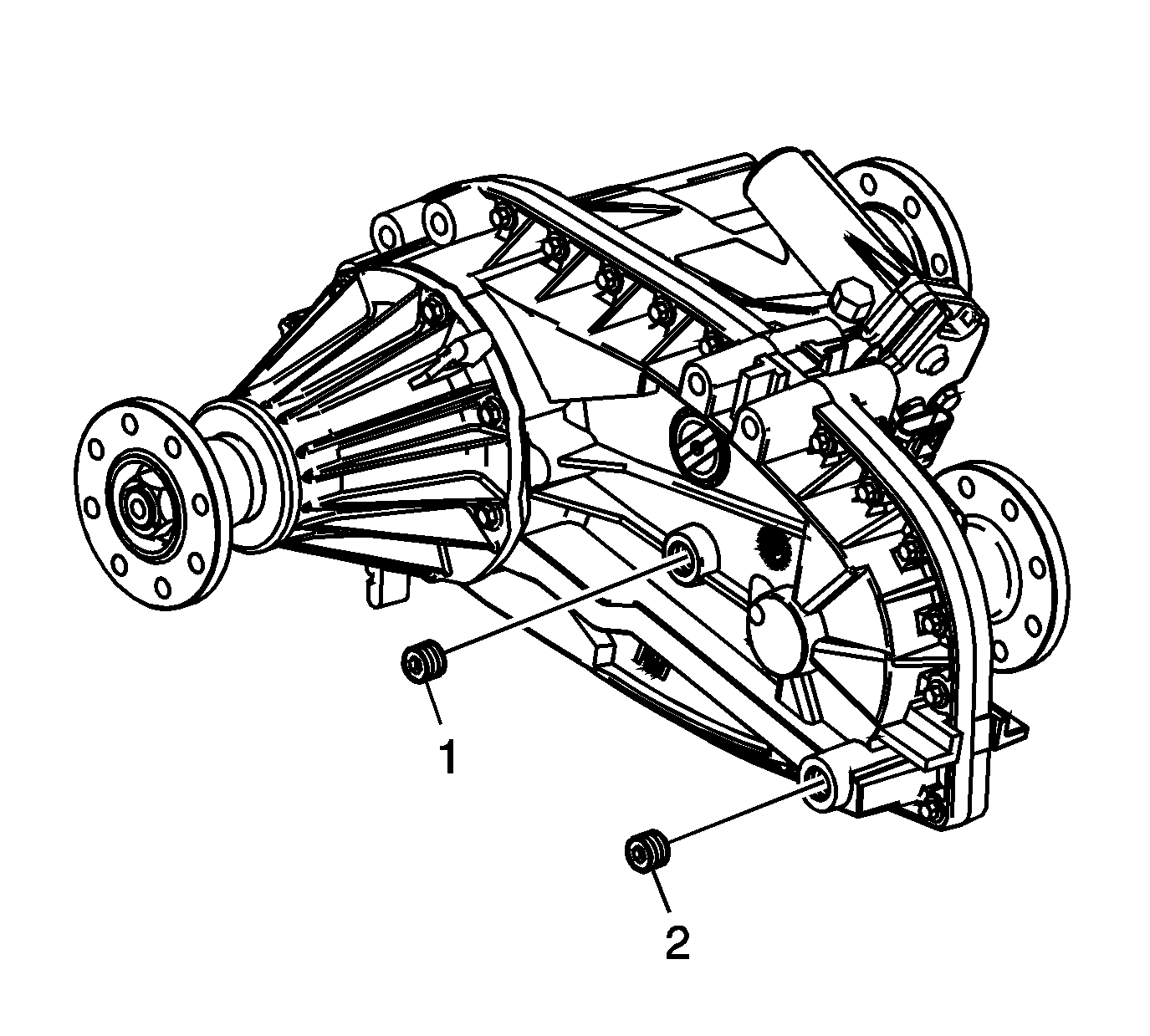
- Remove the drain plug (2) and the fill plug (1).
- Drain the fluid from the transfer case.
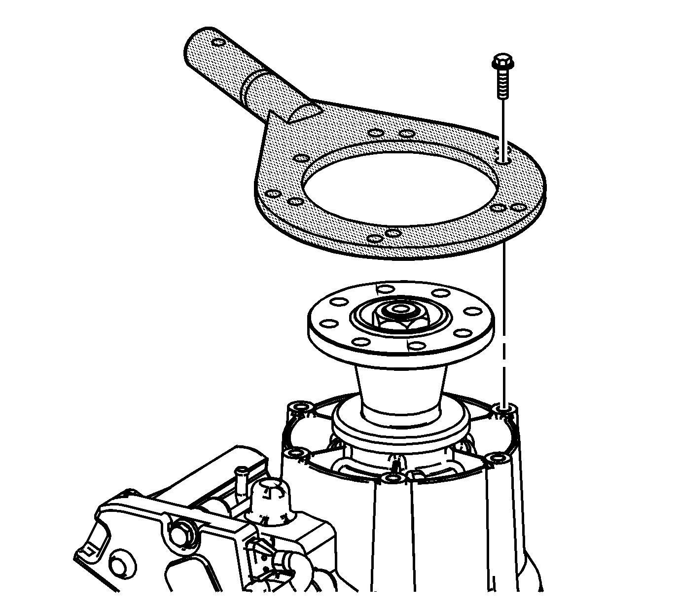
- Attach the J 45759 fixture to the transfer case using 4 suitable bolts. All of the transfer case disassembly procedures can be performed with the case mounted to the J 45759 fixture .
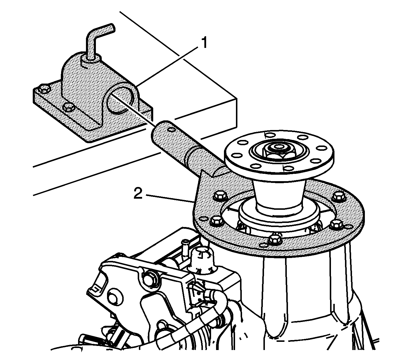
- Mount the J 3289-20 fixture (1) to a sturdy workbench.
- Install the J 45759 fixture (2) into the J 3289-20 fixture (1) and secure with the pivot pin.
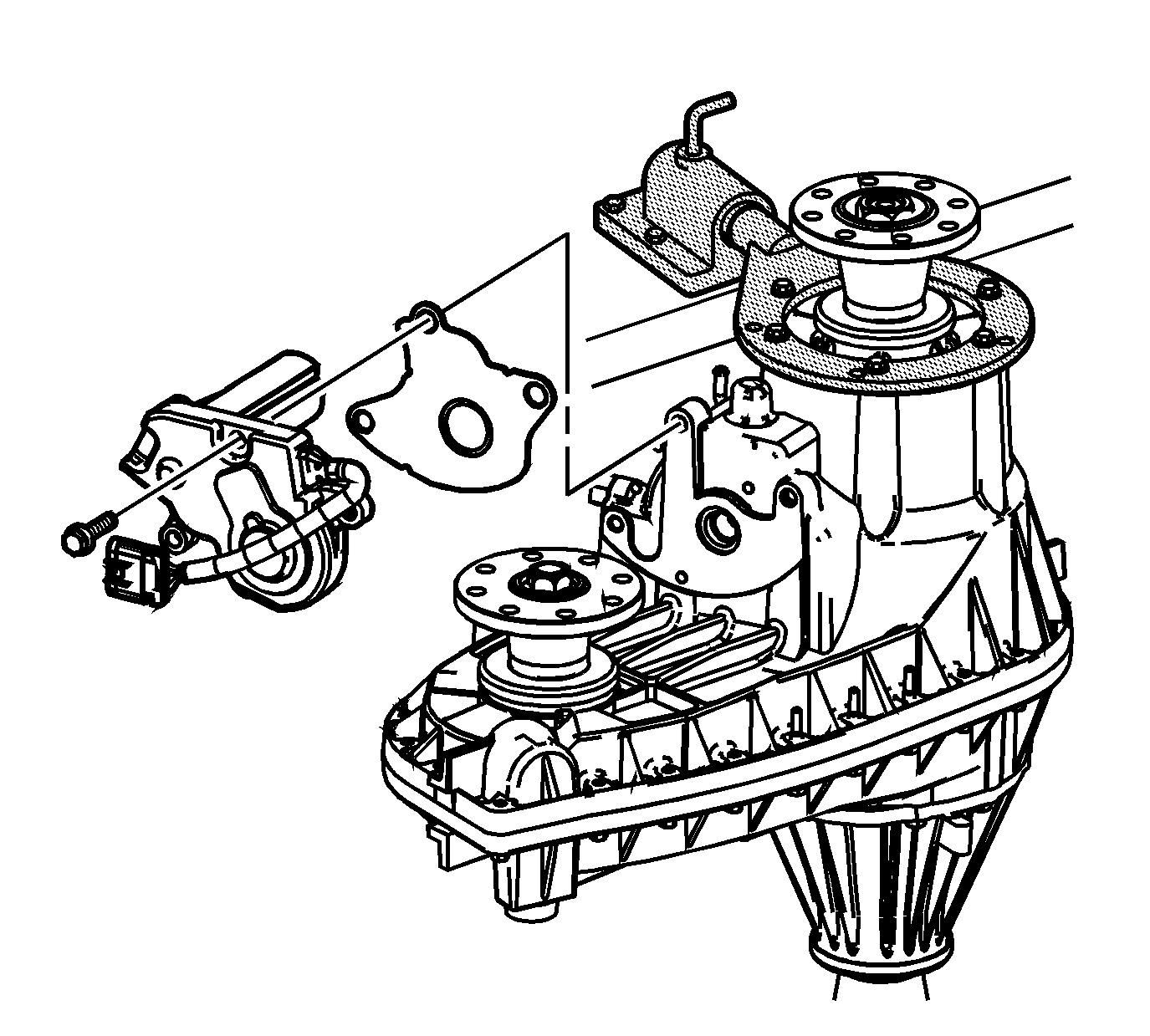
- Remove the actuator encoder motor mounting bolts.
- Remove the actuator encoder motor assembly and bracket.
- Remove the actuator insulator gasket.
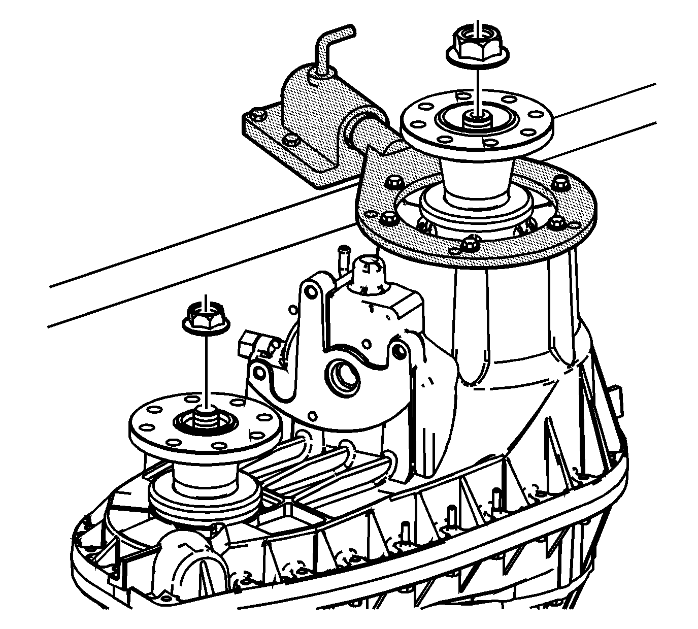
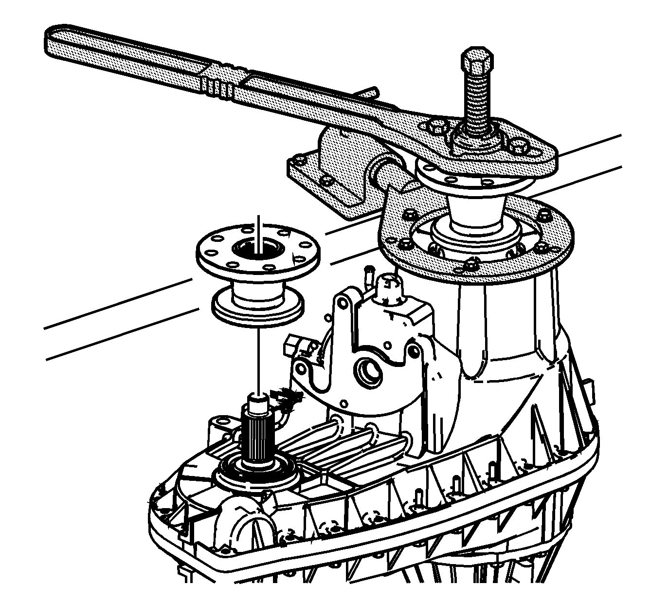
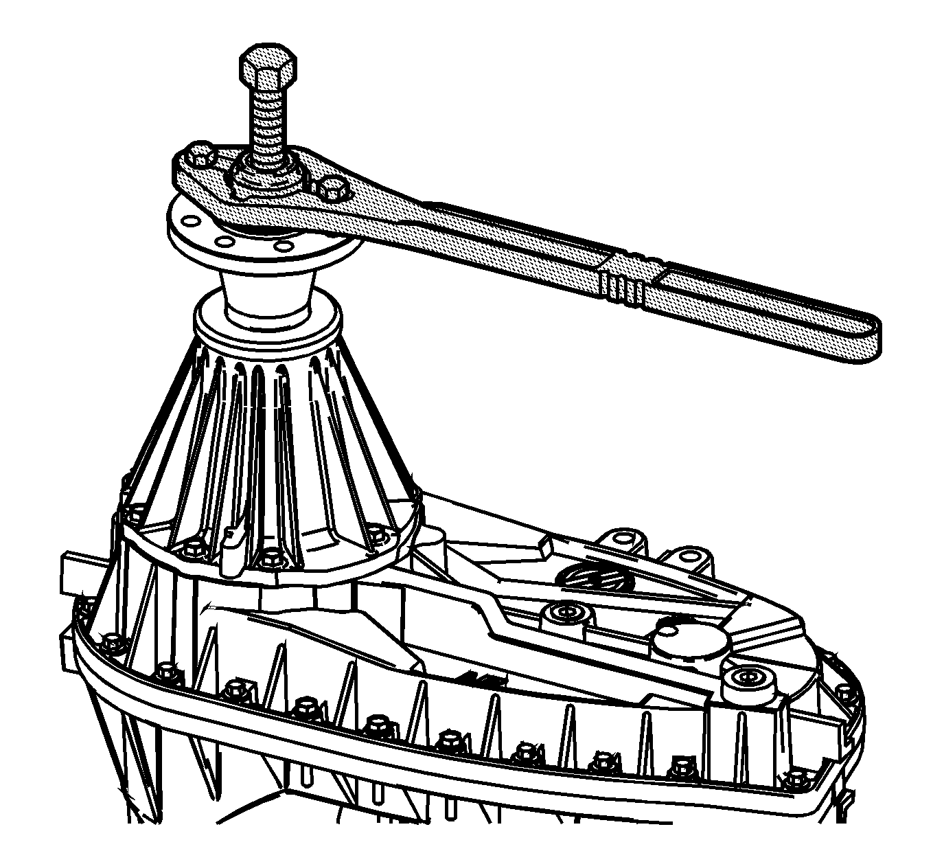
- Remove the front output flange and input flange nuts.
- Using the J 8614-01 holding tool , remove the input flange and front output flange.
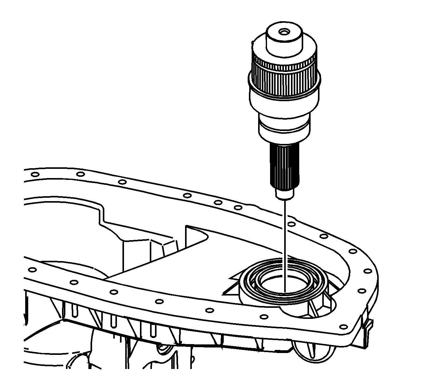
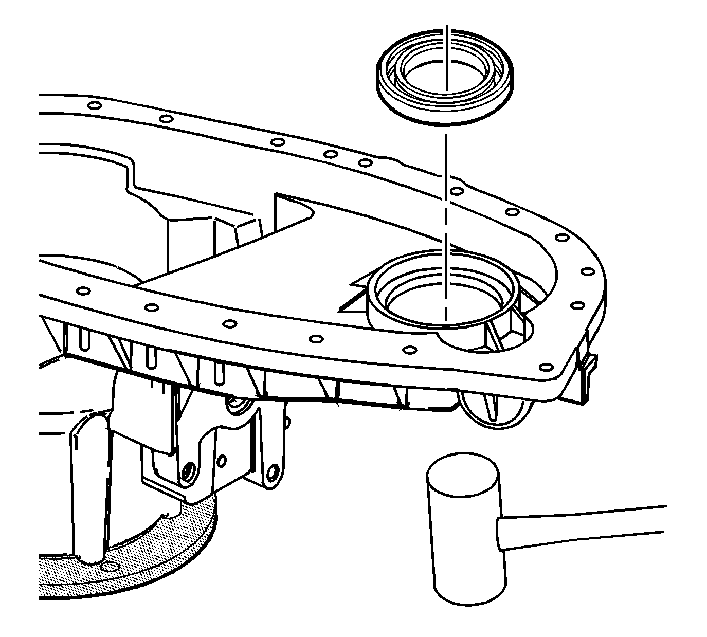
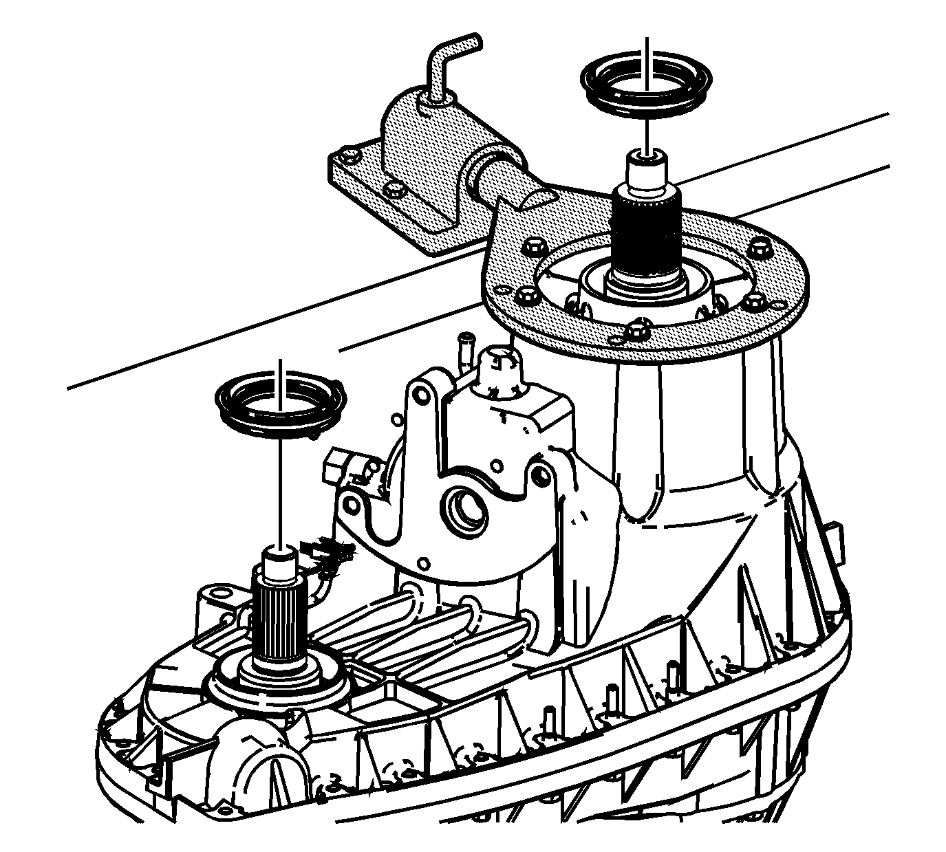
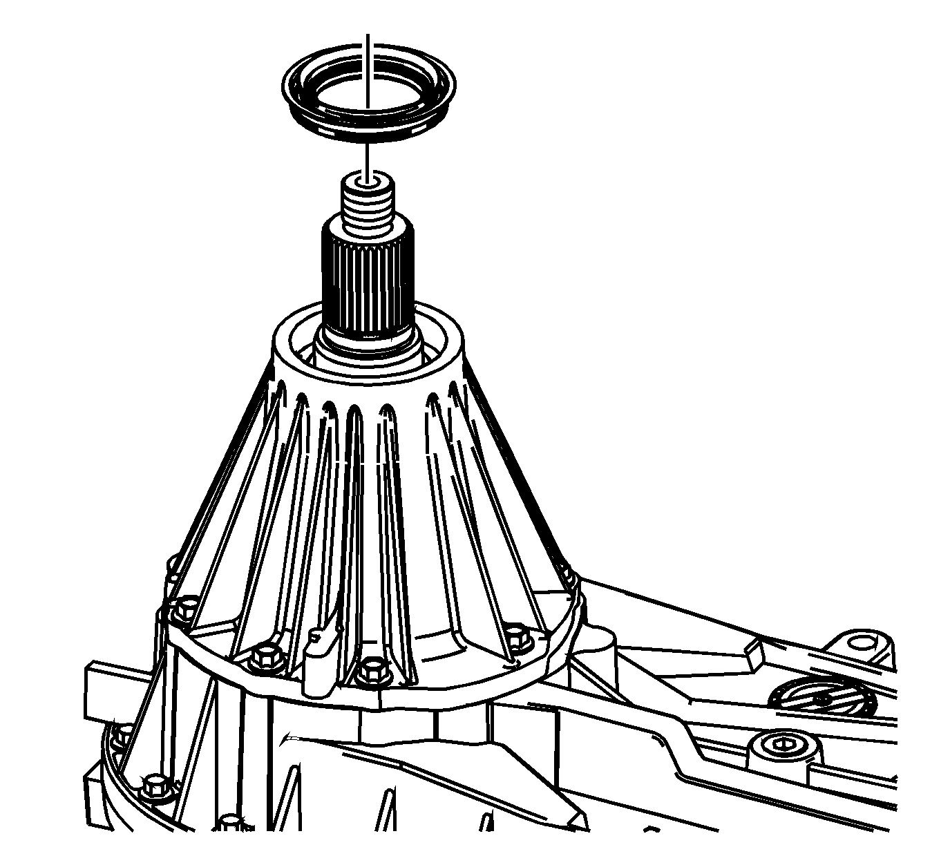
- Remove the input seal.
- Remove the front output seal.
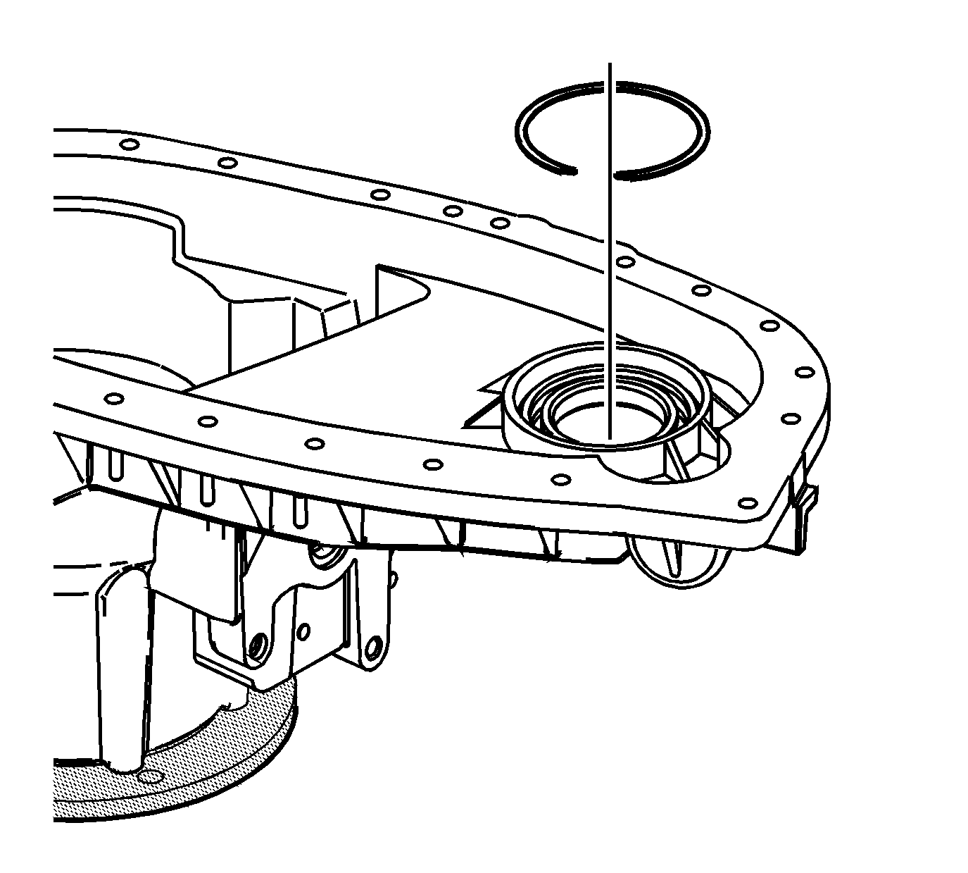
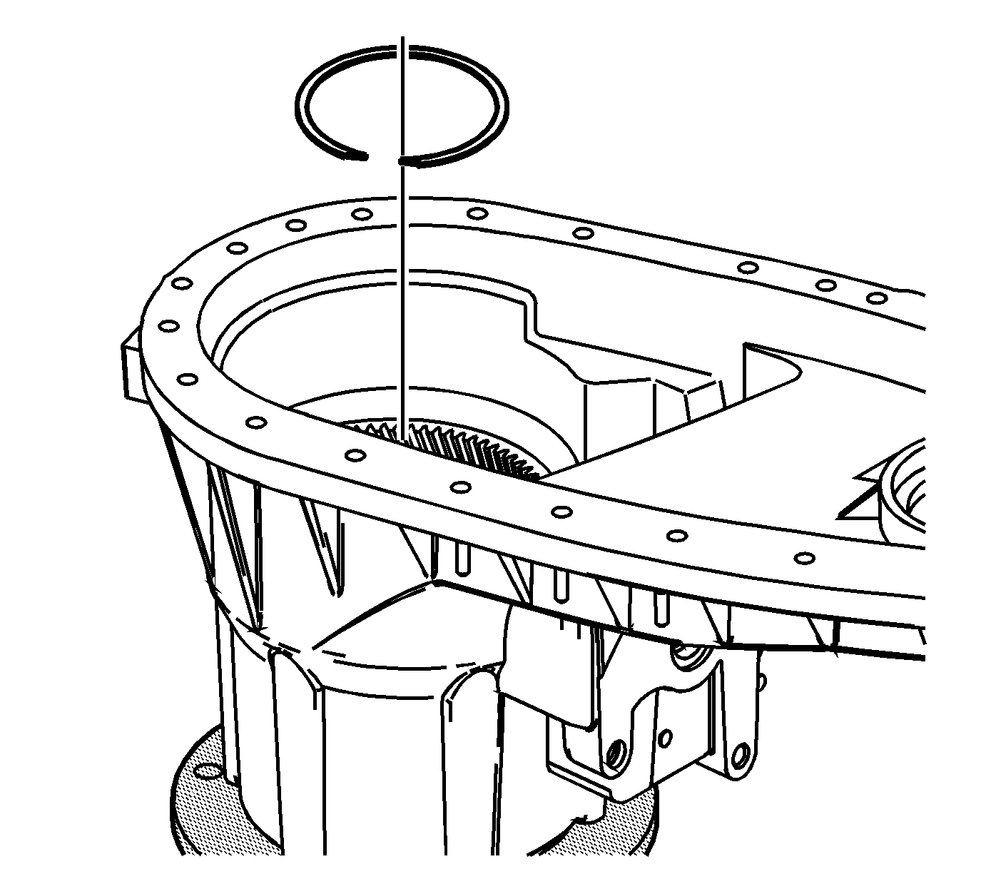
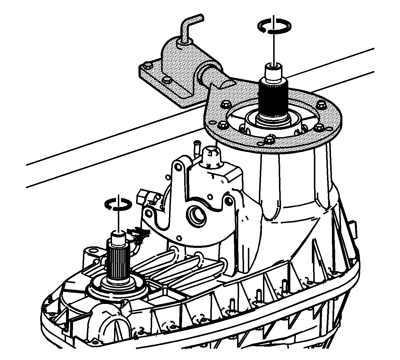
- Remove the input gear bearing inner retaining ring.
- Remove the front output shaft bearing inner retaining ring.
- Rotate the transfer case 180 degrees.
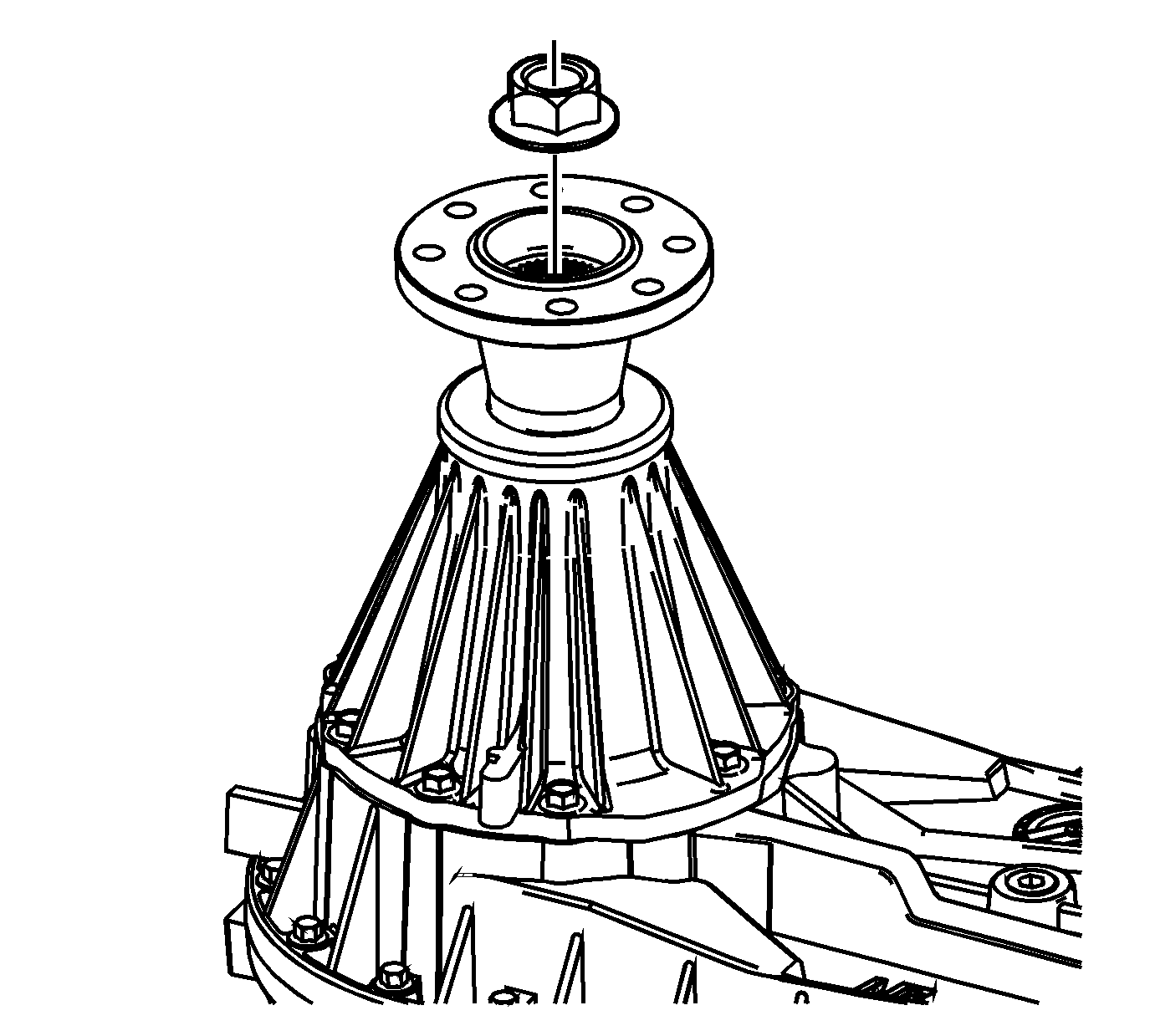
- Remove the rear output flange nut.
- Using the J 8614-01 holding tool , remove the rear output flange.
- Remove the rear output seal.
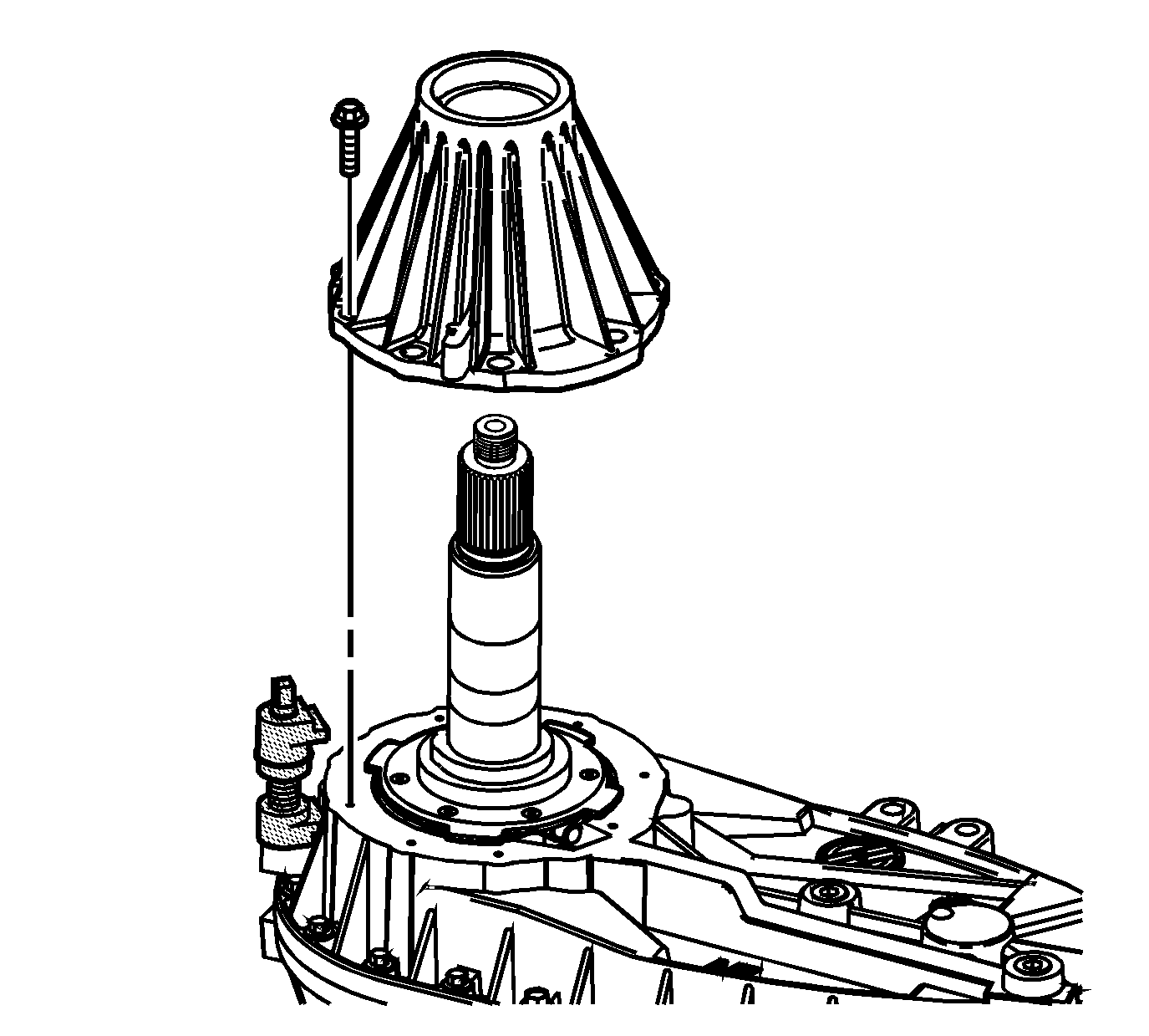
- Remove the retainer assembly bolts.
- Use the J 45358 spreader to remove the retainer assembly.
- Inspect the rear needle bearing for being faulty. Refer to Transfer Case Cleaning and Inspection.
- Remove the rear needle bearing from the retainer assembly, if faulty.
- Using a pair of needle nose pliers, pull the upper connection tube (2) from the oil pump assembly (3).
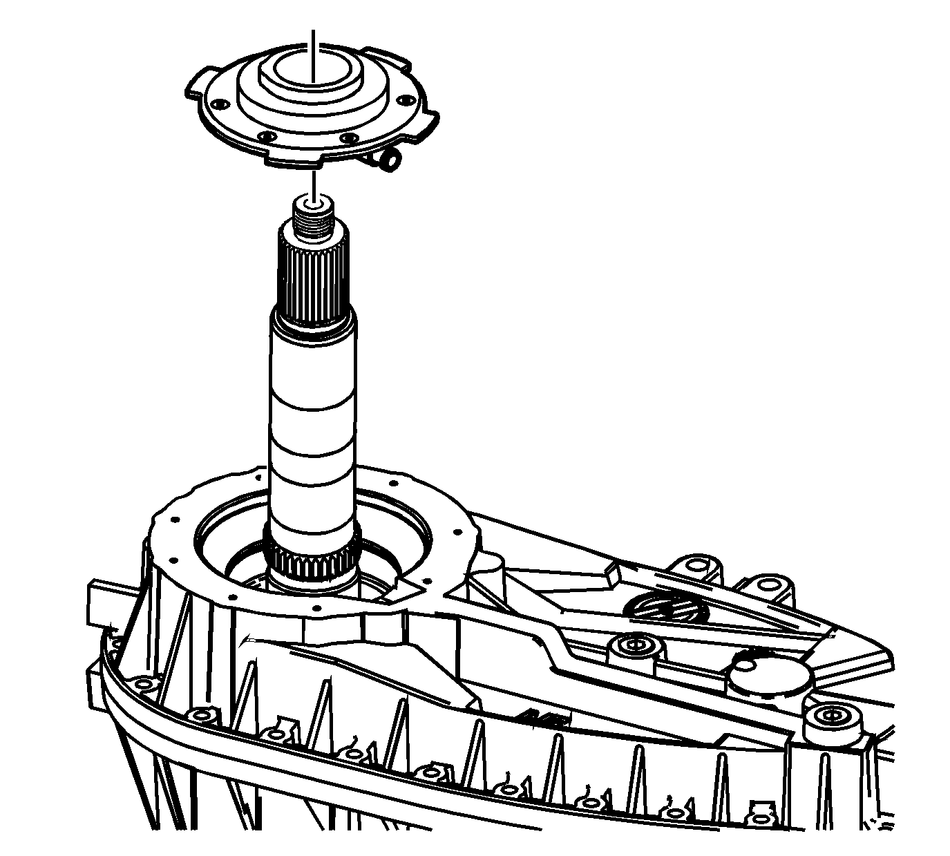
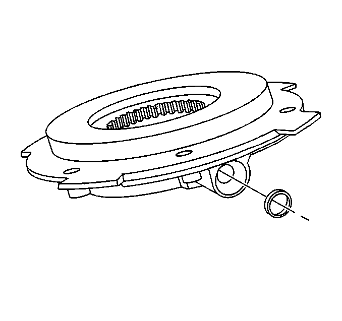
- Remove the oil pump assembly.
- Remove the O-ring seal from the oil pump assembly.
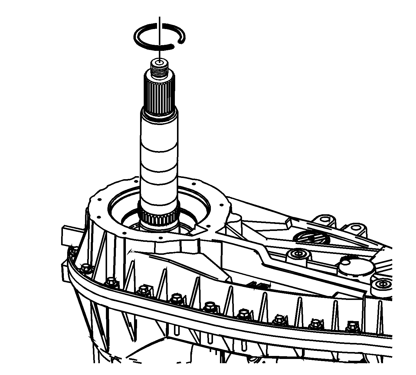
- Remove the rear output bearing inner retaining ring.
- Mark the location of the 3 longer bolts for correct assembly.
- Remove the transfer case retaining bolts.
- Evenly pry the rear case half from the front case half at the locations shown.
- Remove the rear case half from the front case half.
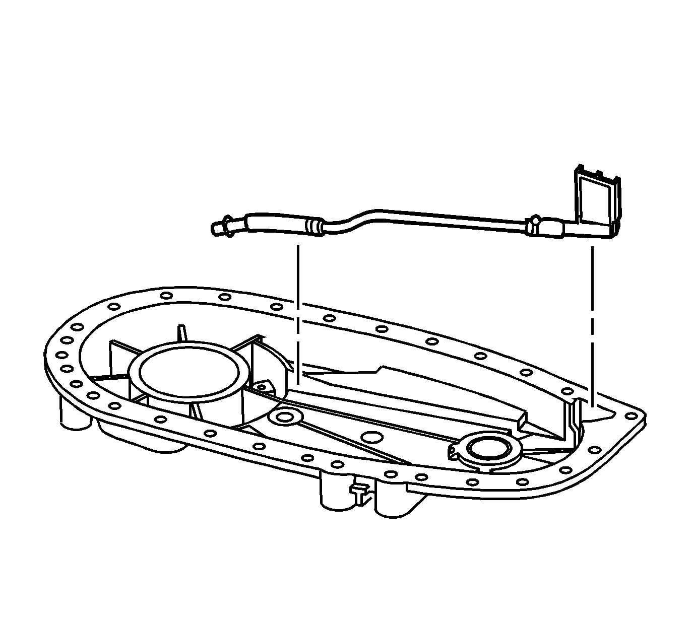
- Remove the oil pump suction pipe and screen from the rear case half.
- Disconnect the connector between the oil pump suction pipe to the oil pump screen.
- Inspect the rear output bearing for being faulty. Refer to Transfer Case Cleaning and Inspection.
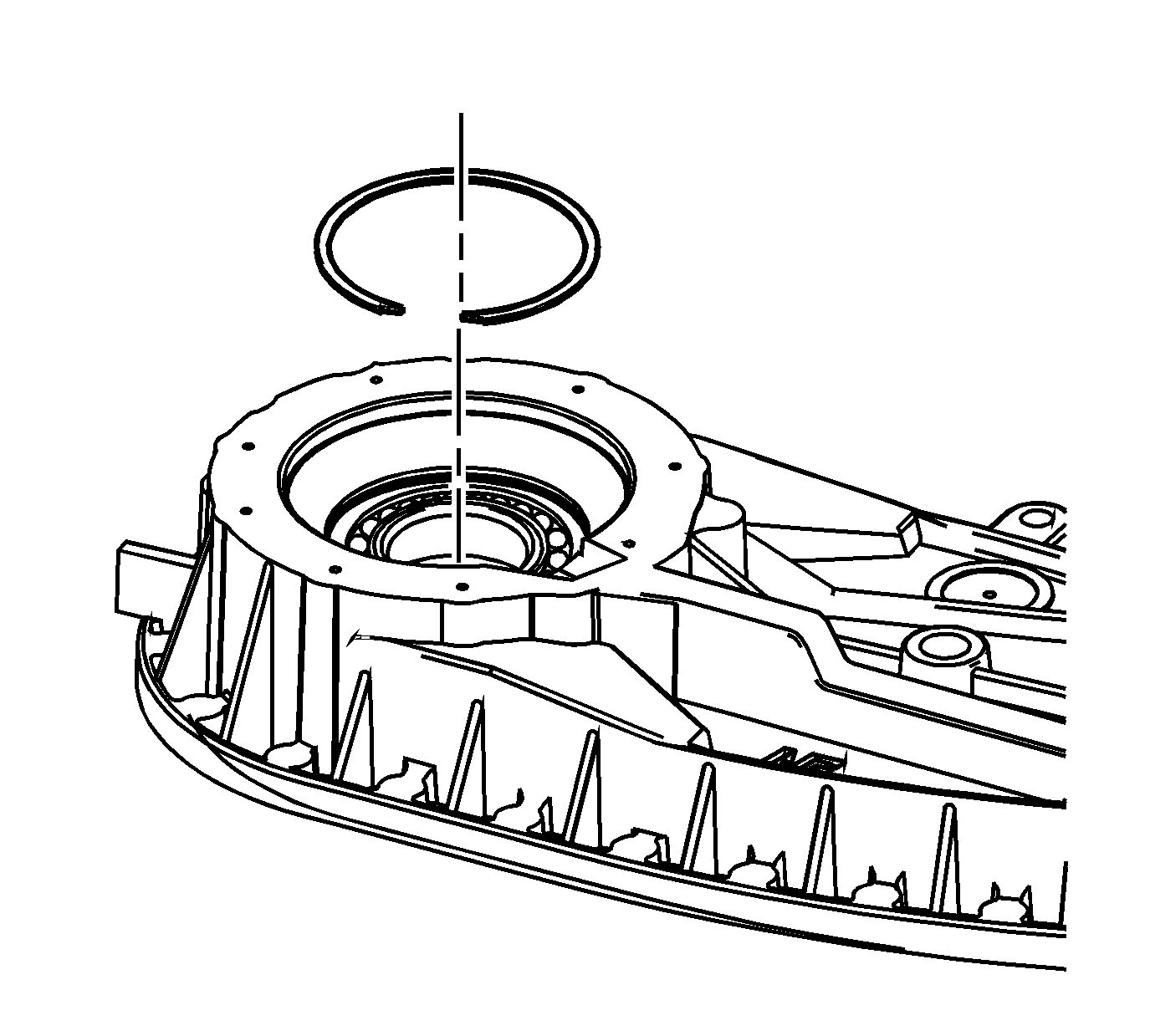
- Remove the rear output bearing outer retaining ring, if the rear output bearing is faulty.
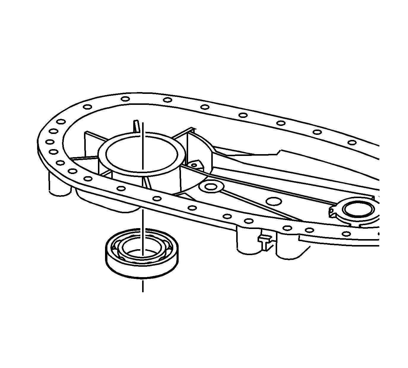
- Remove the rear output bearing from the rear case half, if faulty.
- Inspect the front output needle bearing for being faulty. Refer to Transfer Case Cleaning and Inspection.
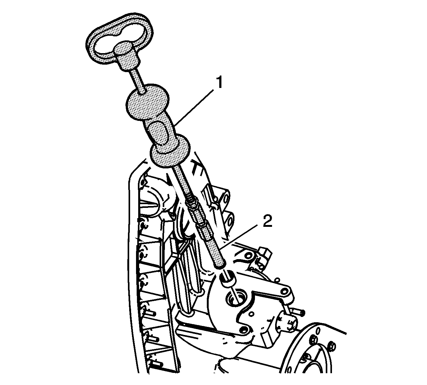
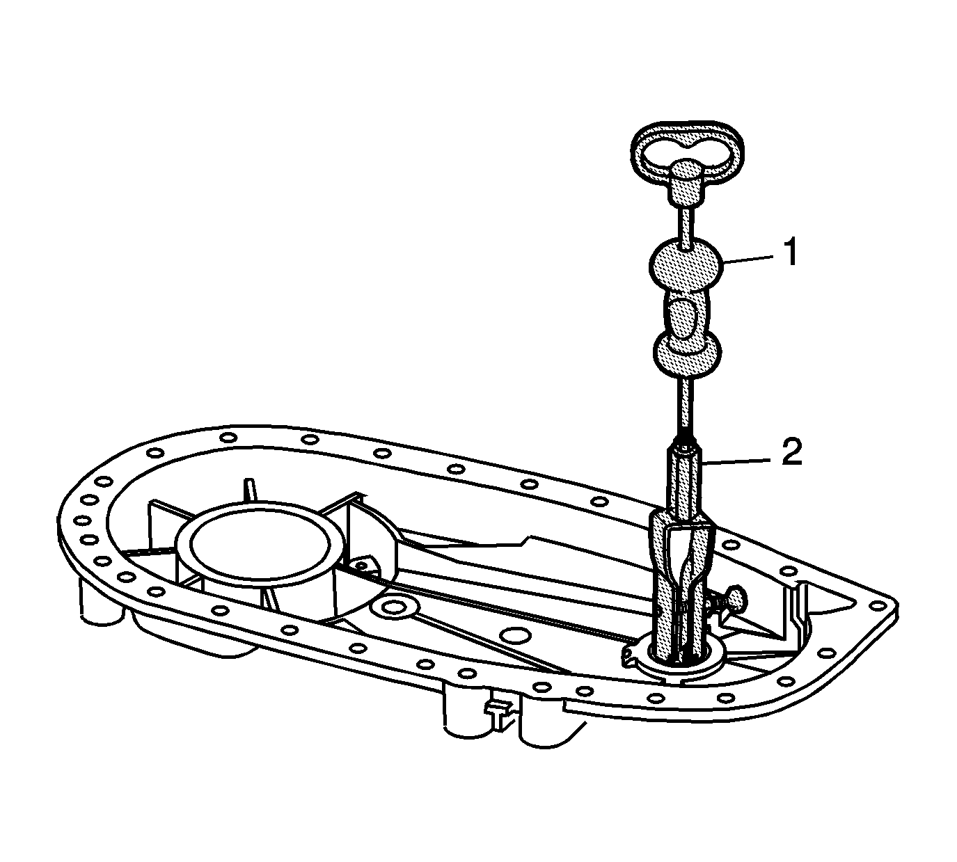
- Using the J-2619-A slide hammer (1) and J 29369-2 remover (2), remove the front output needle bearing from the rear case half, if faulty.
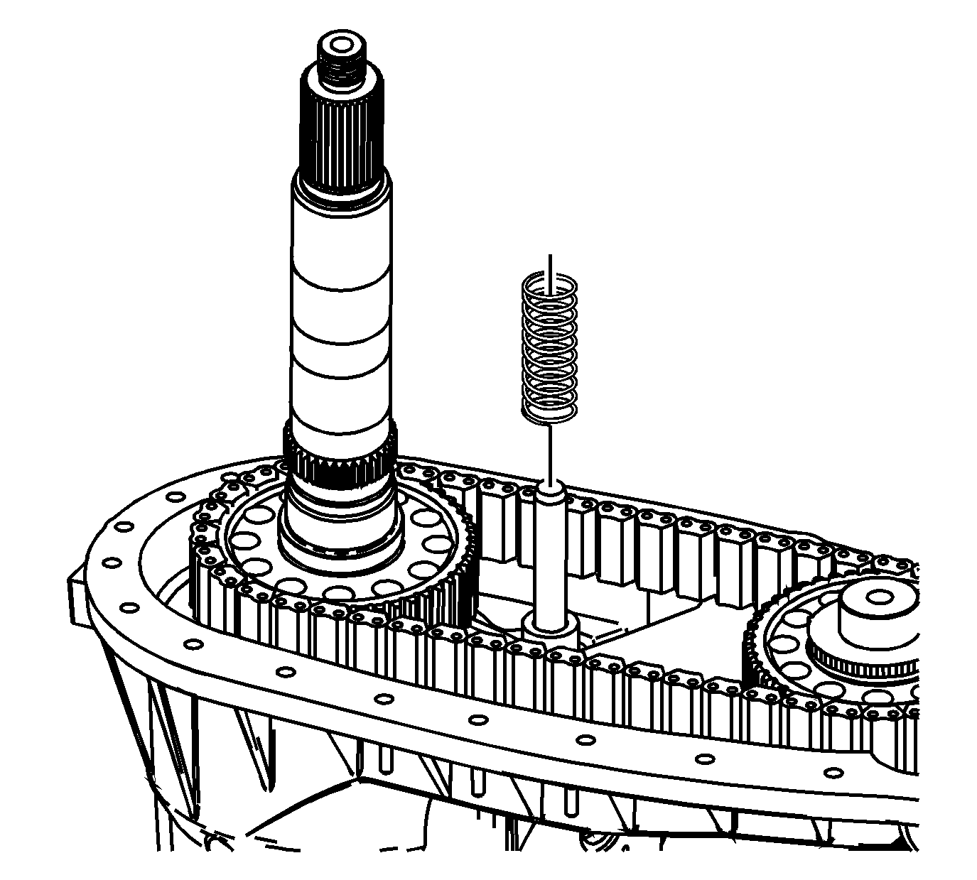
- Remove the shift fork shaft spring.
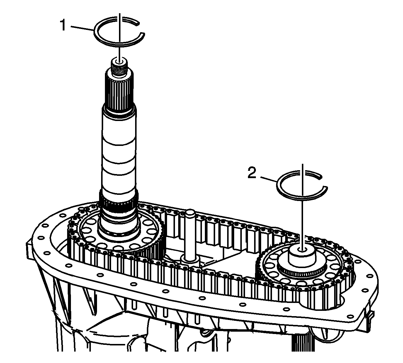
- Remove the drive sprocket retaining ring (1).
- Remove the driven sprocket retaining ring (2).
- Remove the drive chain and the sprockets from the mainshaft and the front output shaft.
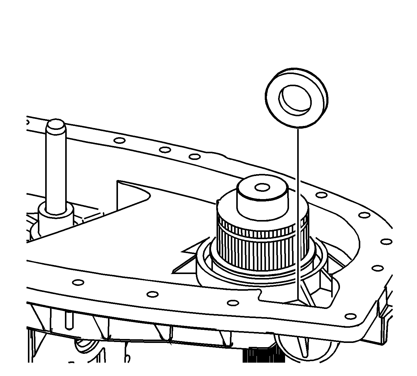
- Remove the magnet.
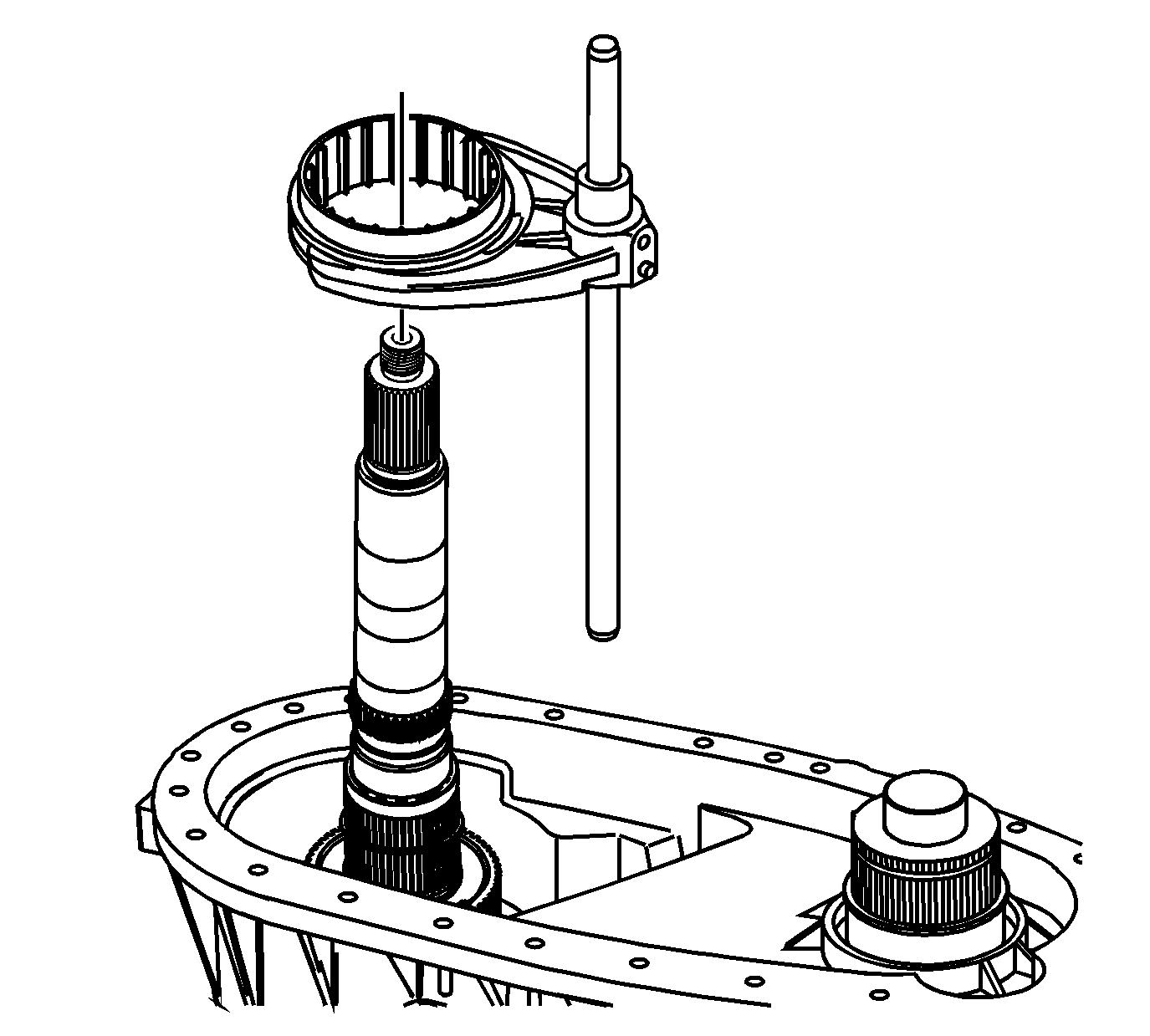
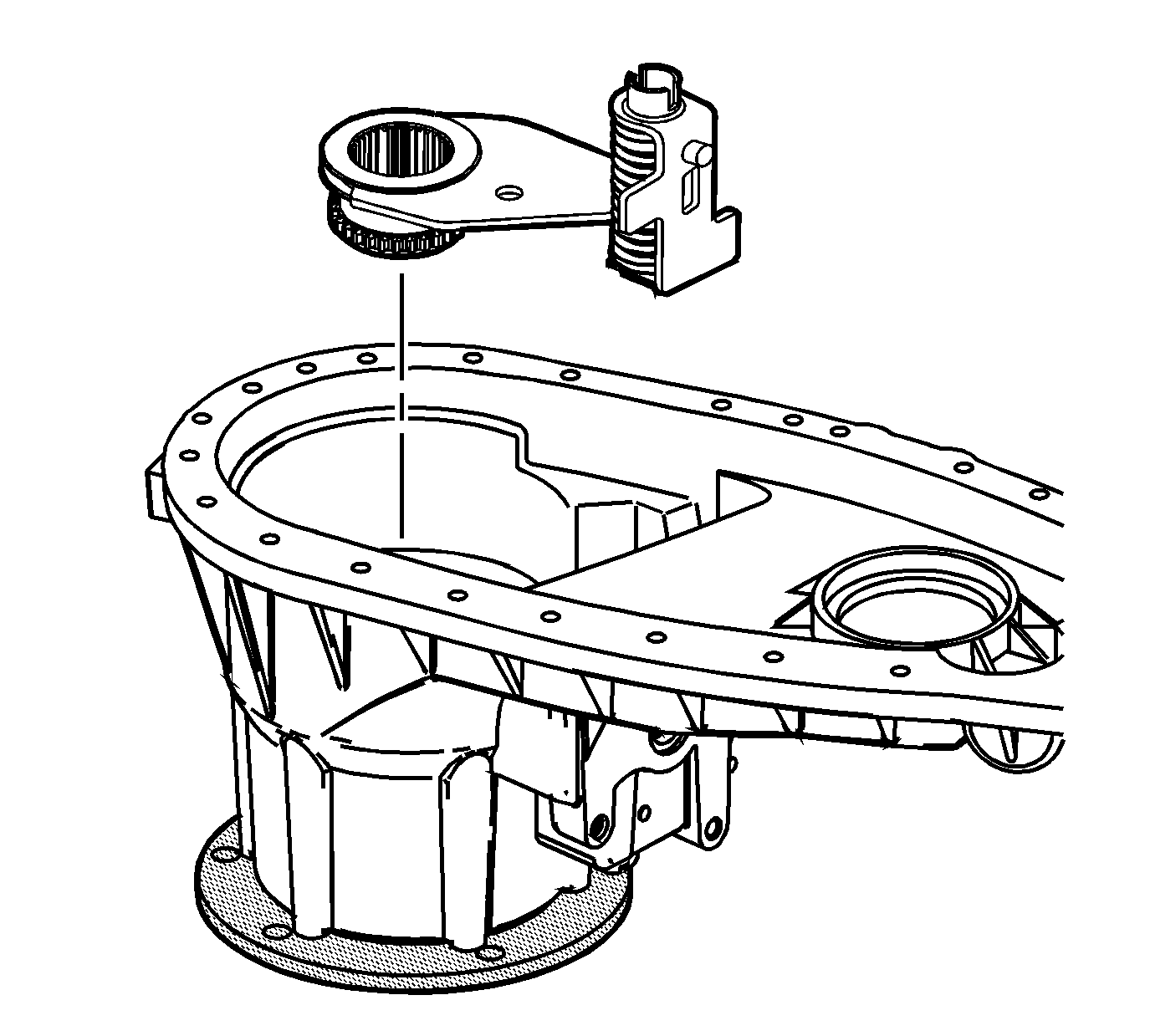
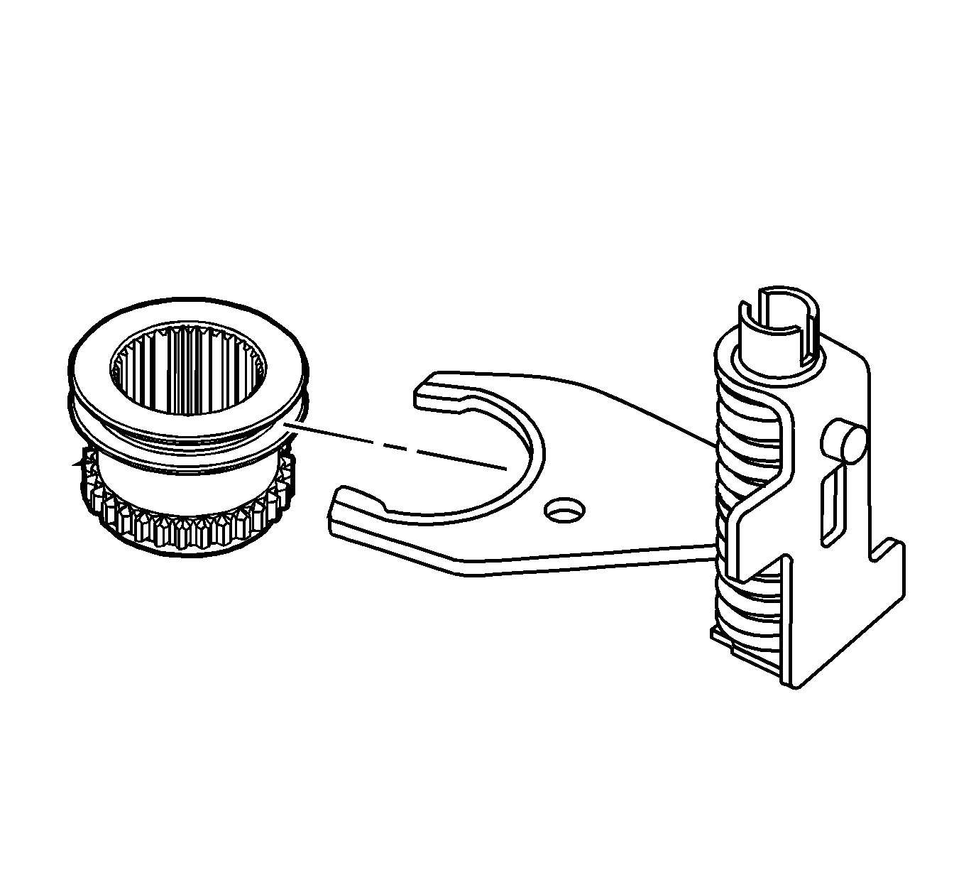
- Remove the synchronizer sleeve and the shift fork as an assembly.
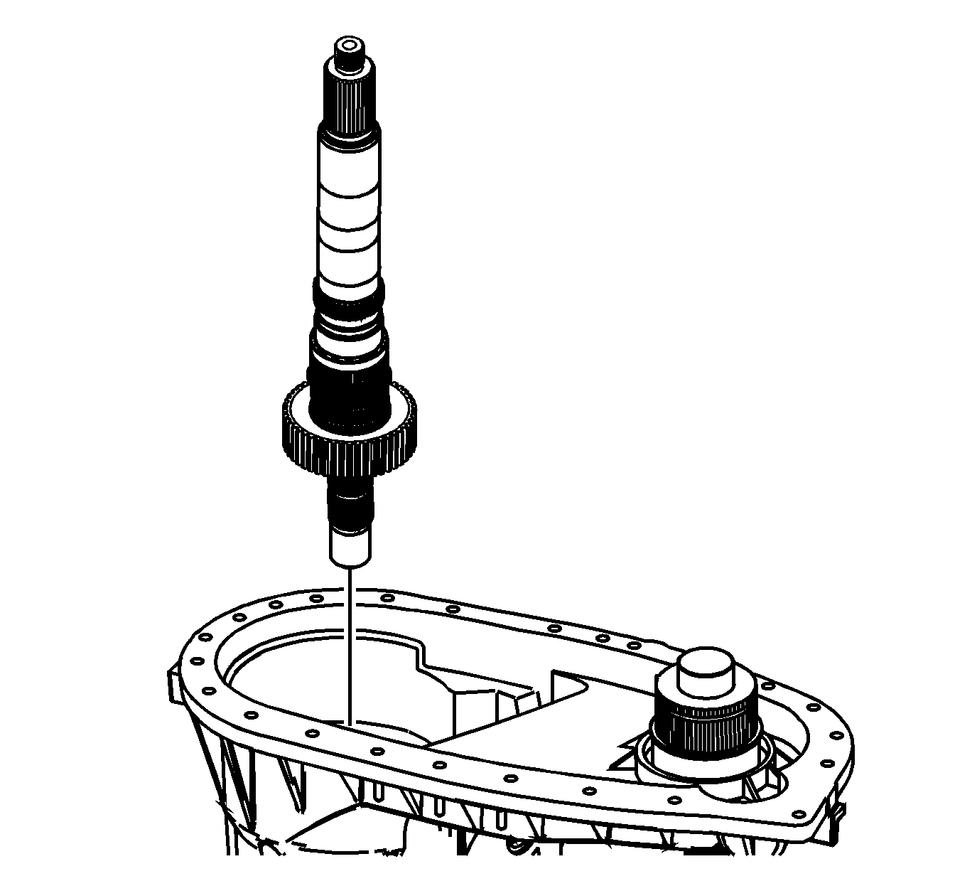
- Remove the mainshaft assembly.
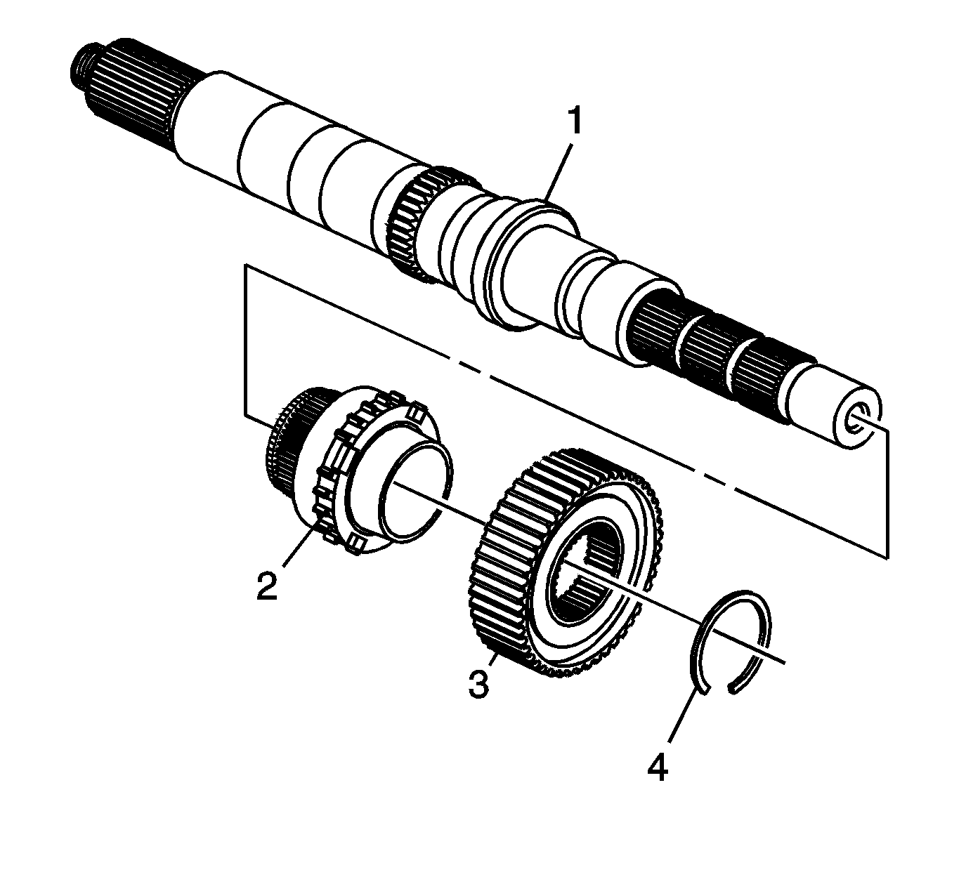
- Remove the synchronizer hub retaining ring (4) from the mainshaft (1).
- Remove the synchronizer hub (3).
- Remove the 2/4 wheel drive synchronizer gear (2) from the mainshaft (1).
- Remove the high/low range sleeve and the shift fork.
- Remove the range sleeve from the shift fork.
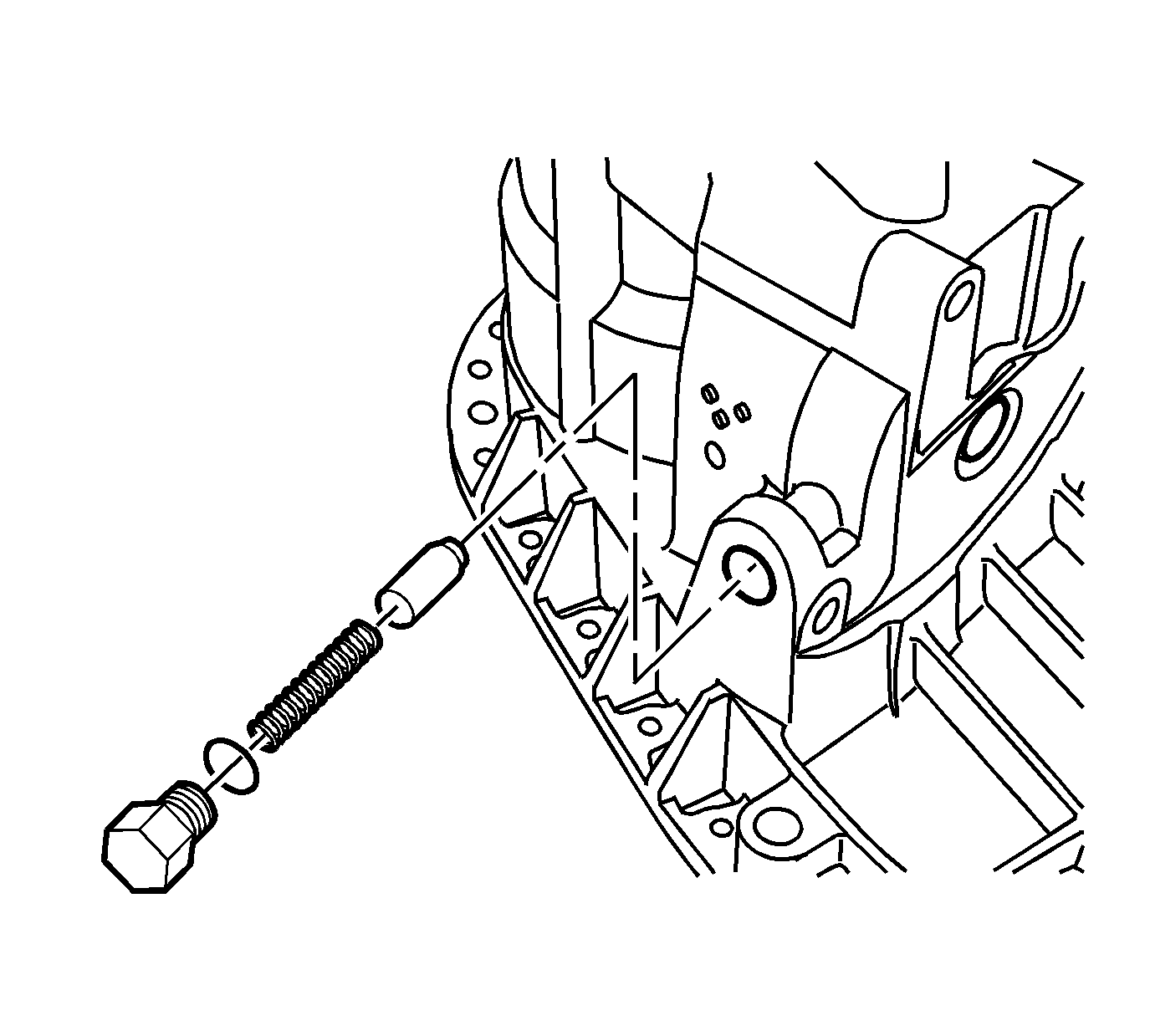
- Remove the shift detent assembly.
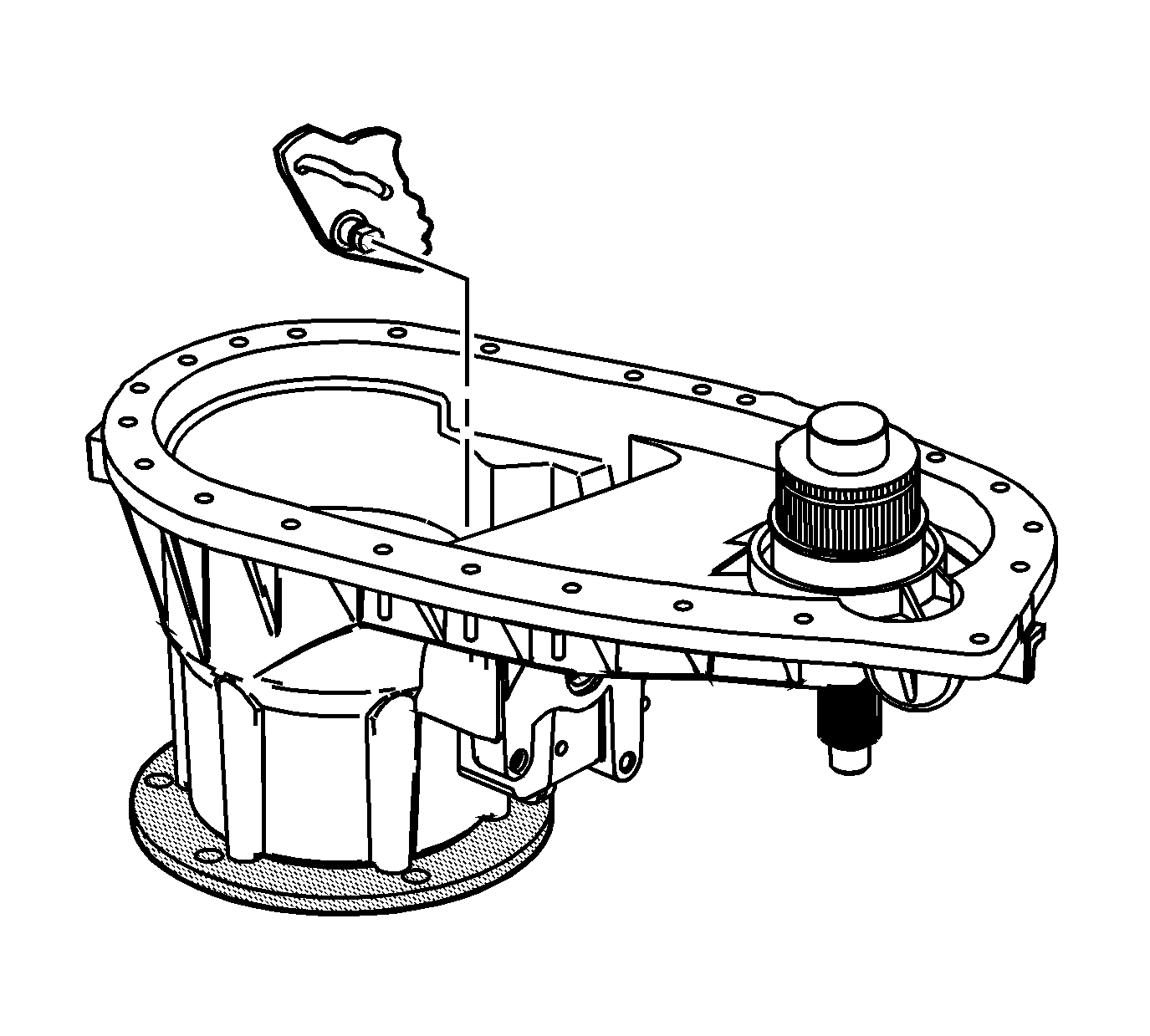
- Remove the sector assembly.
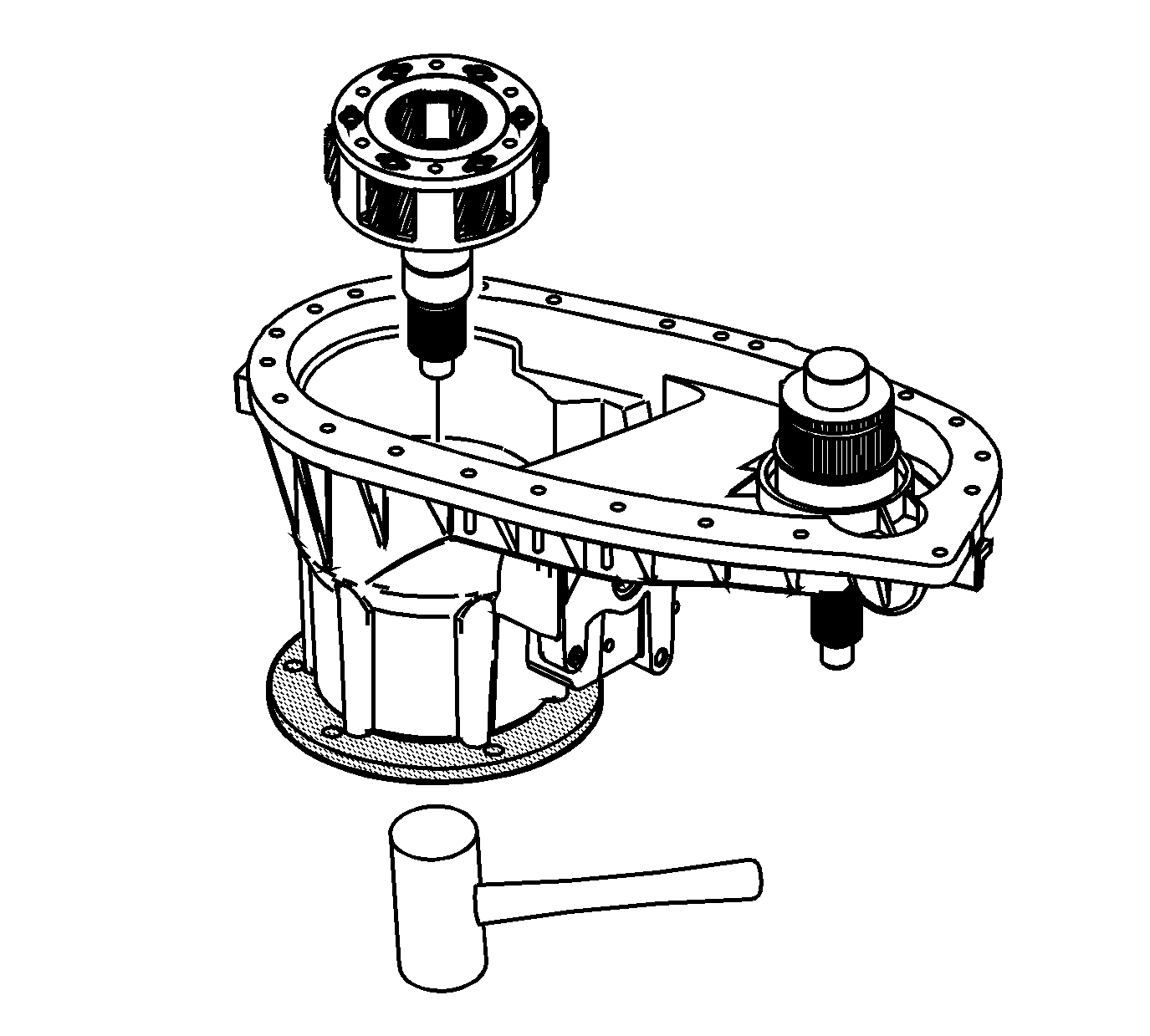
- Using a soft-face hammer, remove the high/low planetary assembly.
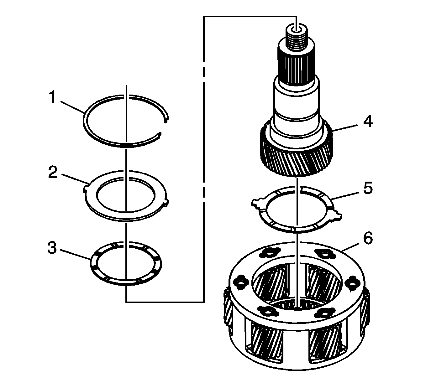
- Remove the planetary carrier lock plate retaining ring (1).
- Remove the planetary carrier lock plate (2).
- Remove the input gear front thrust washer (3).
- Remove the input gear (4).
- Remove the input gear rear thrust washer (5).
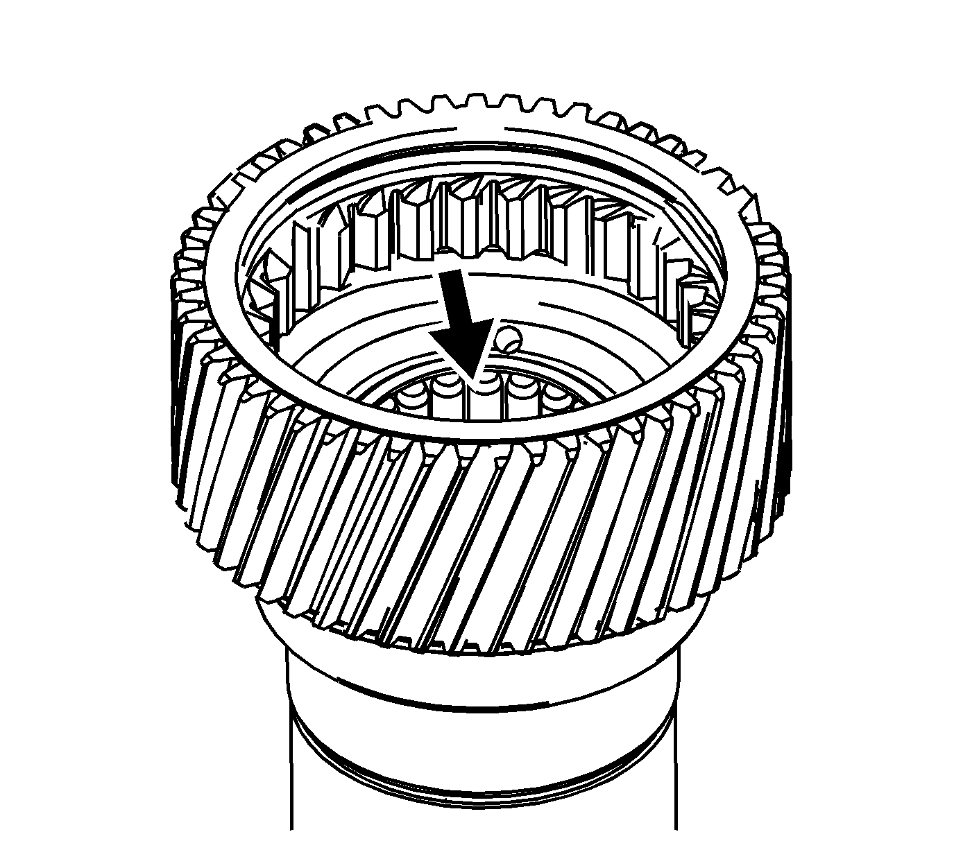
- Inspect the needle bearing in the input gear for being faulty. Refer to Transfer Case Cleaning and Inspection.
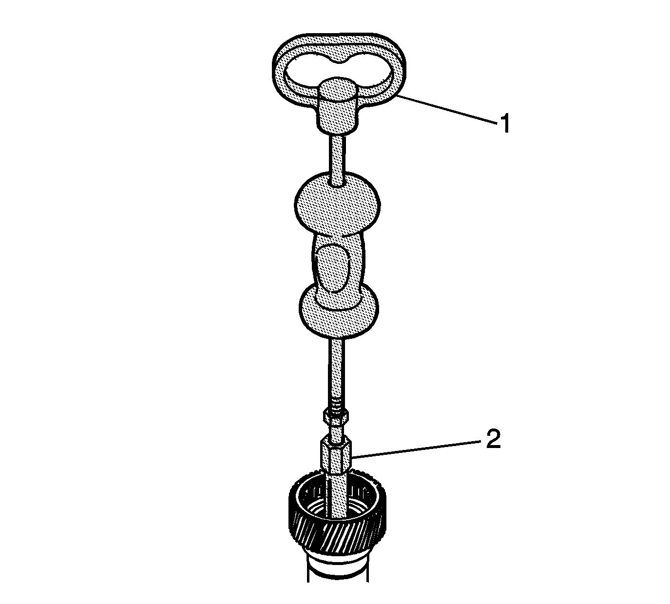
- Using the J-2619-A slide hammer (1) and J 44738 remover (2), remove the needle bearing from the input gear, if faulty.
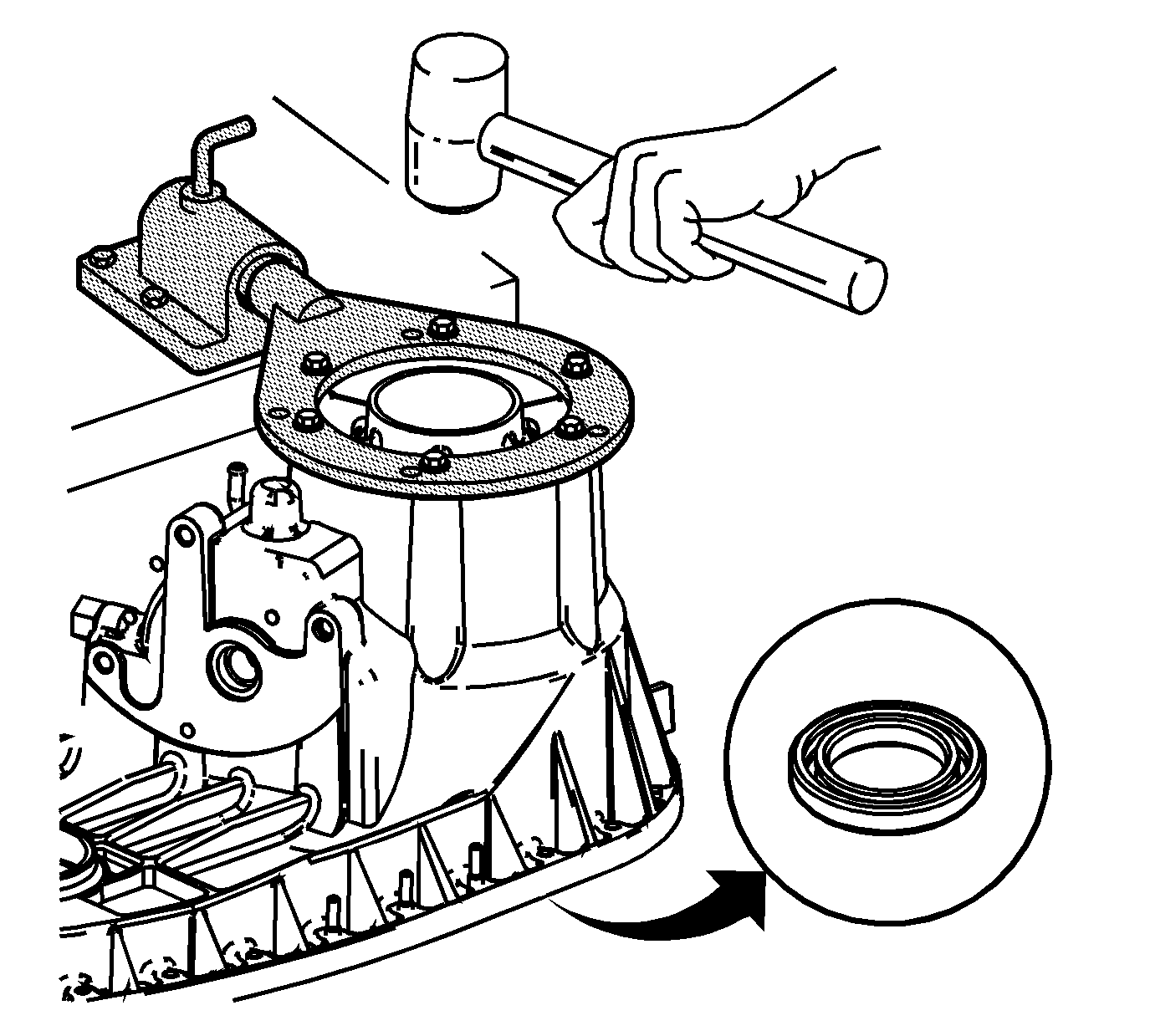
- Using a soft-face hammer, remove the front output shaft from the front case half.
- Inspect the front output shaft bearing for being faulty. Refer to Transfer Case Cleaning and Inspection.
- Remove the front output shaft bearing outer retaining ring, if the front output shaft bearing is faulty.
- Remove the front output shaft bearing from the front case half, if faulty.
- Inspect the input gear bearing for being faulty. Refer to Transfer Case Cleaning and Inspection.
- Remove the input gear bearing outer retaining ring, if the input gear bearing is faulty.
- Remove the input gear bearing from the front case half, if faulty.
- Inspect the sector bearing for being faulty. Refer to Transfer Case Cleaning and Inspection.
- Using the J-2619-A slide hammer (1) and the J 44737 remover (2), remove the sector bearing from the front case half if faulty.
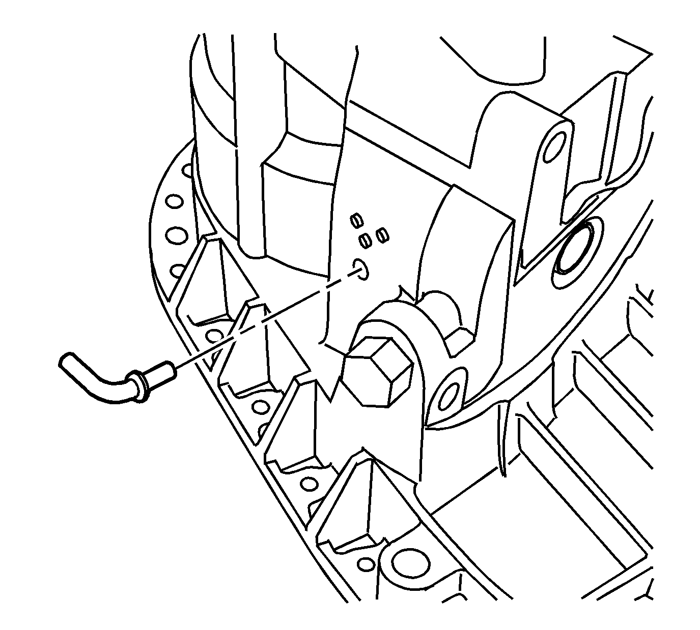
- Remove the vent tube, ONLY if the vent tube elbow is damaged.
Caution: Refer to Transfer Case Seal Removal Caution in the Preface section.
Caution: Refer to Transfer Case Seal Removal Caution in the Preface section.
Caution: Refer to Machined Surface Damage Caution in the Preface section.
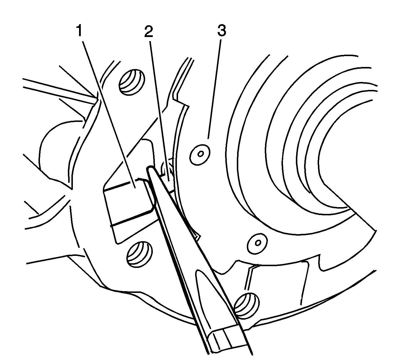
Note: Do not grasp the upper connection hose (1).
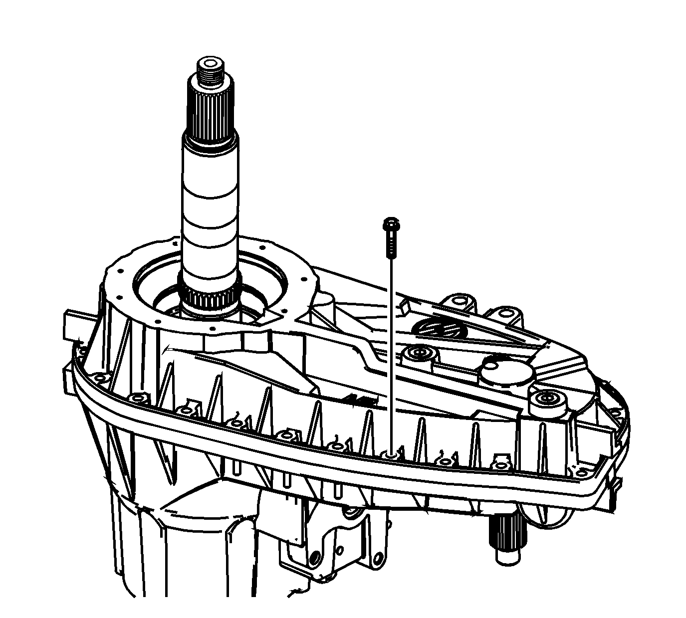
These bolts are for assembly plant use.
Caution: Refer to Machined Surface Damage Caution in the Preface section.
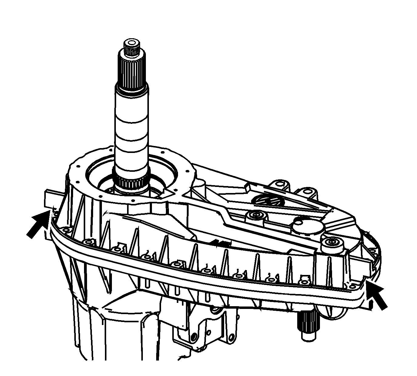
It may be necessary to insert a block between the ears to pry against.
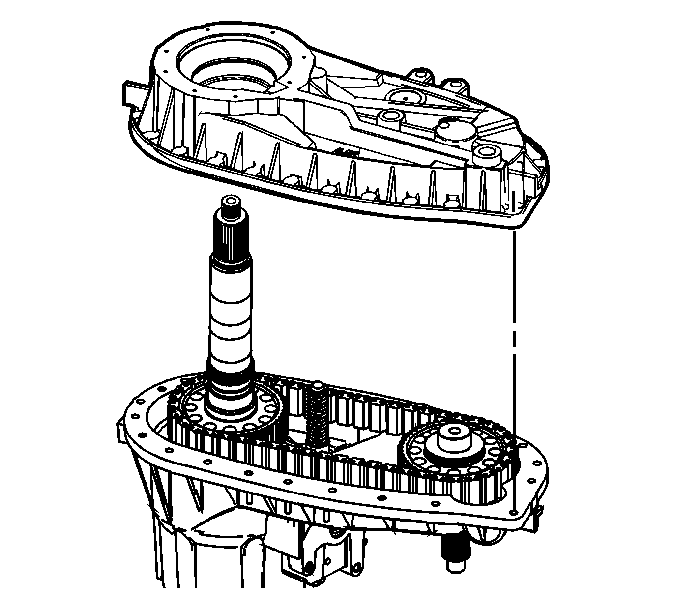
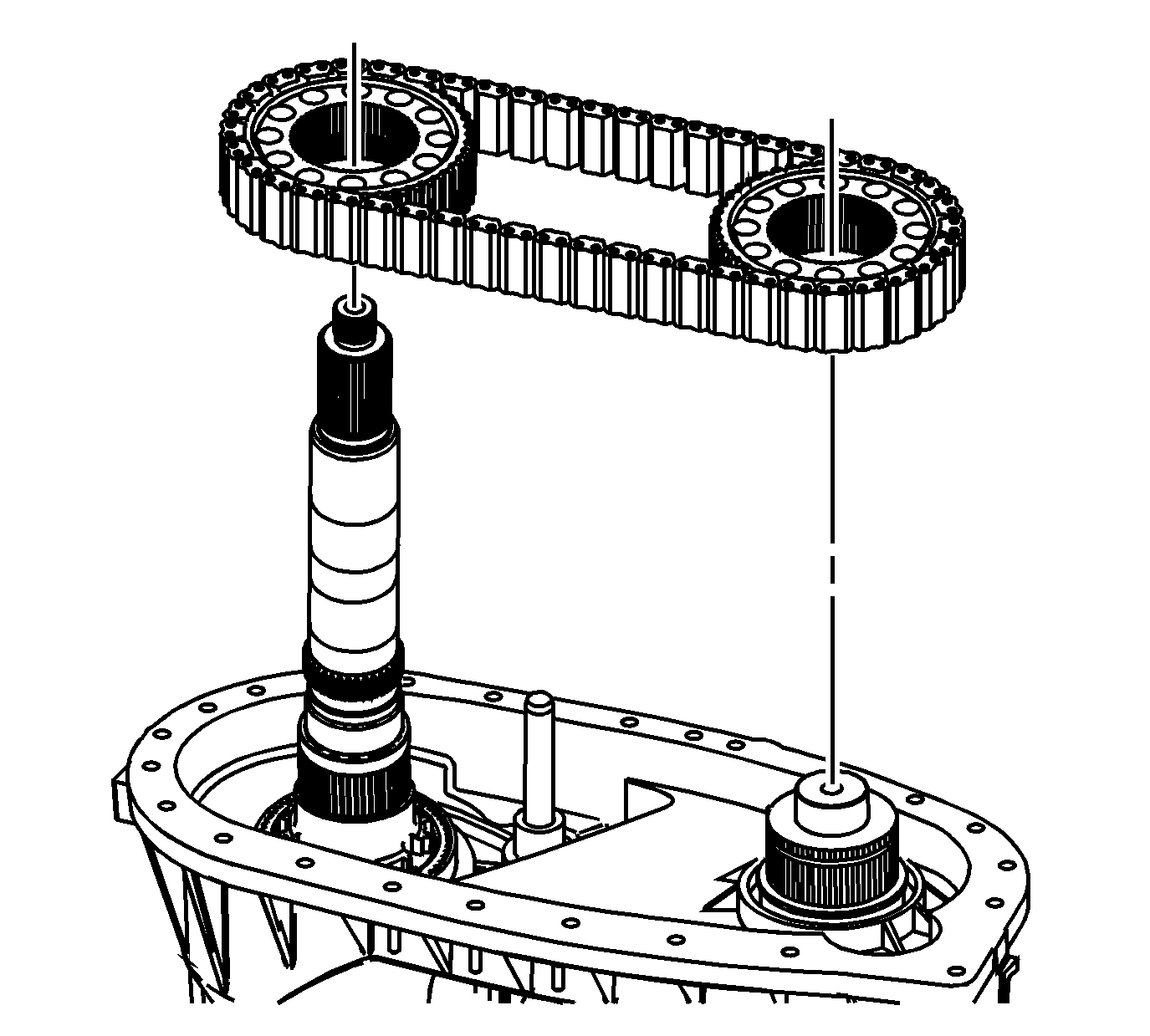
Note: If the drive chain and sprockets are to be used again, mark the position of the drive sprockets with the darkened link on the drive chain, in order to ensure that any wear patterns will be matched for proper installation.
