GM Service Manual Online
For 1990-2009 cars only
Makes
🢒
Chevrolet
🢒
2007
🢒
Kodiak C-Series (Conventional) C4/C5
🢒
Power and Signal Distribution
🢒
Wiring Systems and Power Management
🢒 Air Antilock Brake System Schematics
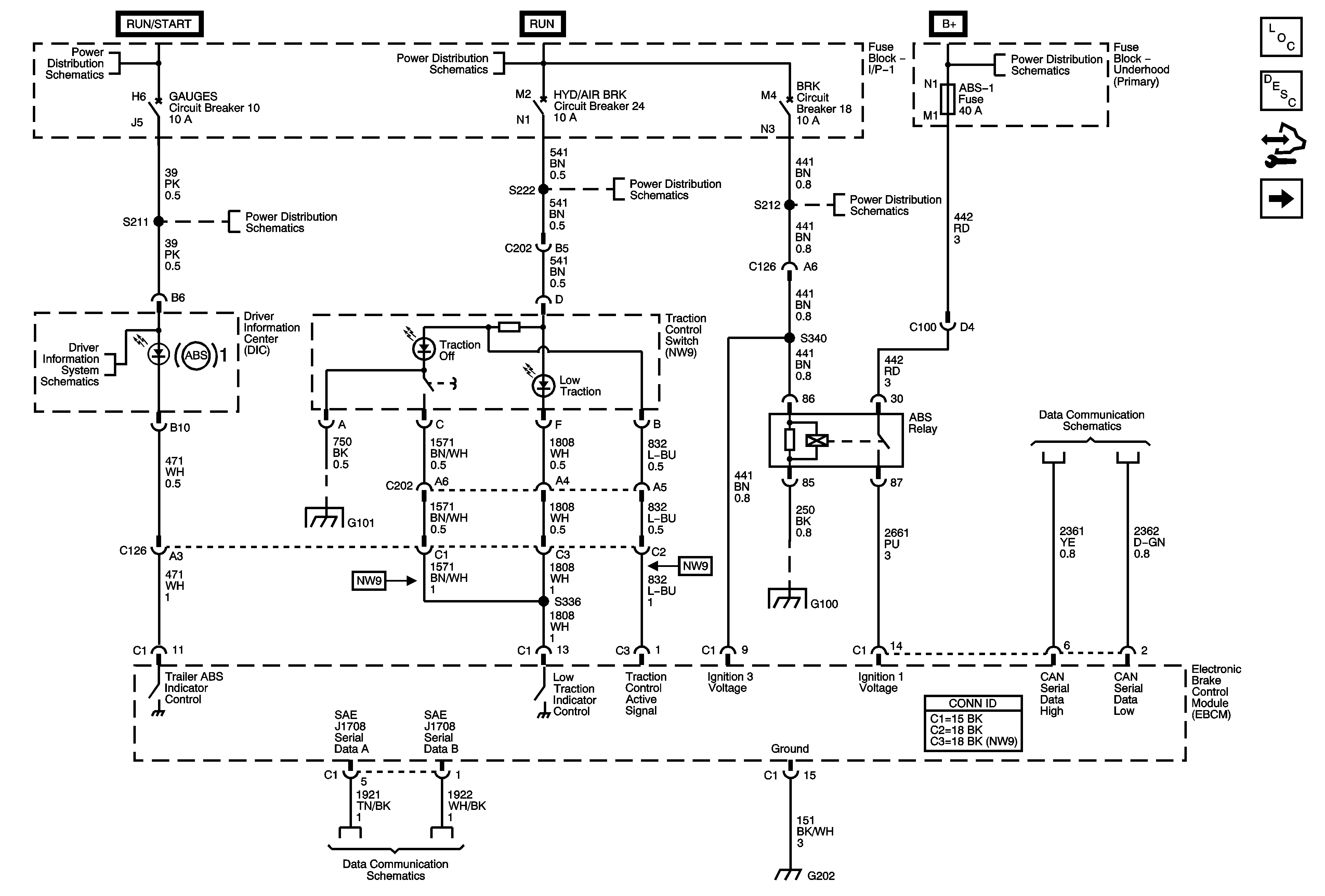
Figure
1:
ABS Relay, DIC and EBCM
Master Electrical Component List
Air ABS Description and Operation
Control Module References
Stop Lamp Switch
Ignition Switch - OFF/RUN/START, RUN/START, and START Busses
2007 MD-560C Driver Information System Schematics - DIC
AIRBAG, GAUGES, LT REAR TURN/STOP, and RT REAR TURN/STOP Fuses/Circuit Breakers
G101 - 2 of 2
Ignition Switch - RUN and ACC/RUN Busses
AXL/4WD, BRK, HYD/AIR BRK, and HTR/AC Fuses/Circuit Breakers
G100 - L18
Data Link Connector Power and Ground
G103 - 2 of 2
Batteries - LG4/LG5 and B+ Bus
J1939 Serial Data, 2 of 2 - L18 w/JE4, LG4, LG5
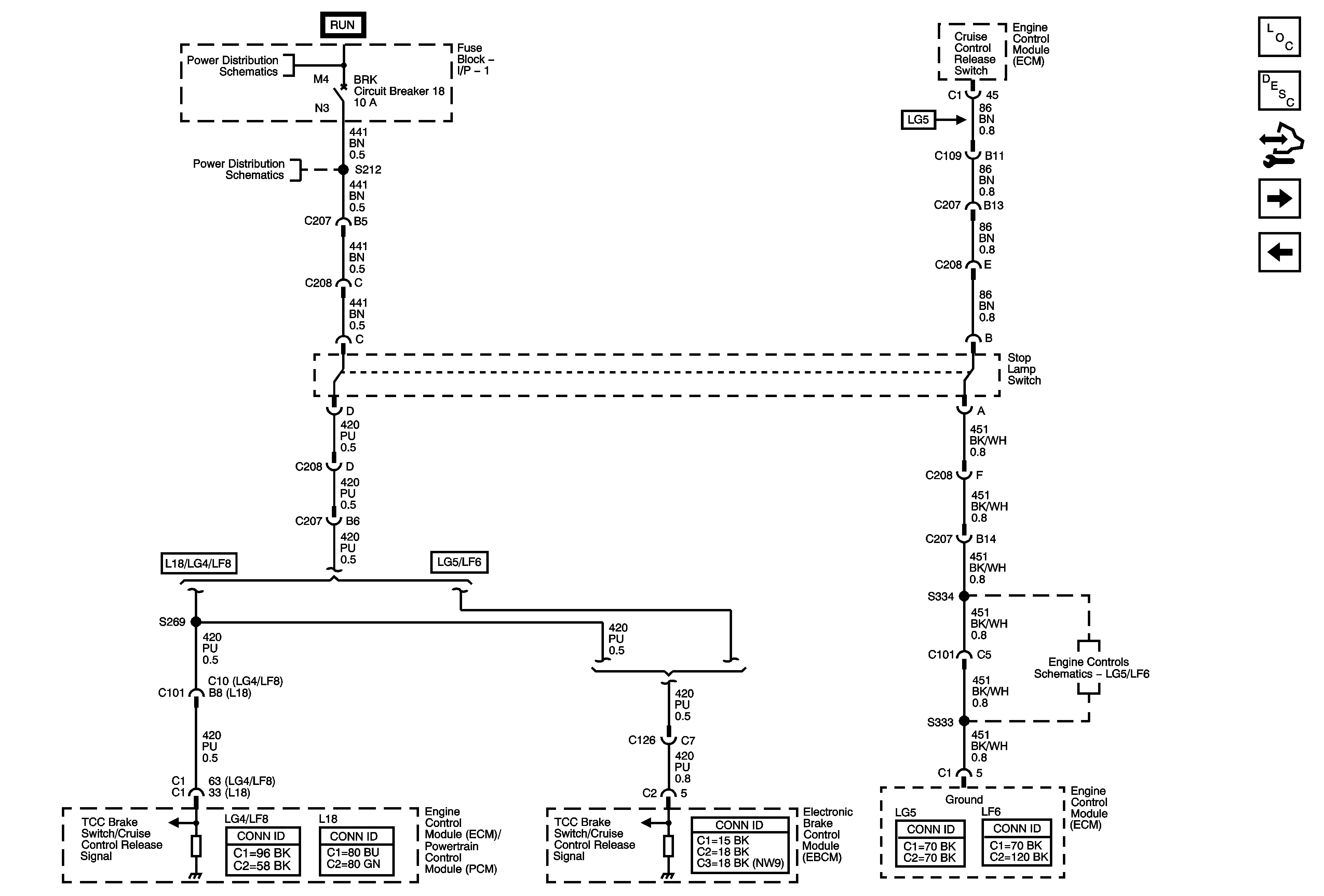
Figure
2:
Stop Lamp Switch
Master Electrical Component List
Air ABS Description and Operation
Control Module References
BPMV and WSS
ABS Relay, DIC and EBCM
Ignition Switch - RUN and ACC/RUN Busses
AXL/4WD, BRK, HYD/AIR BRK, and HTR/AC Fuses/Circuit Breakers
Ground
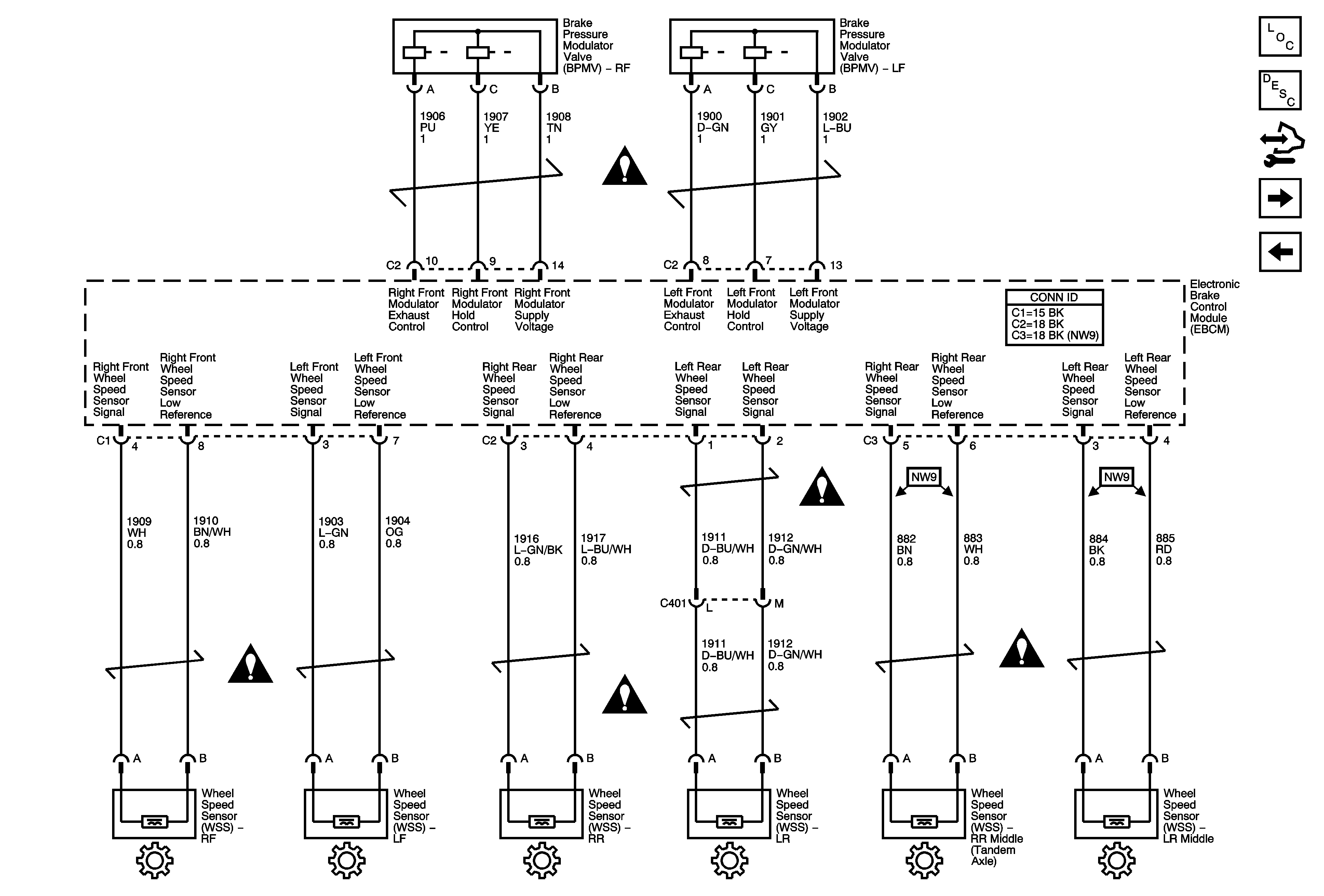
Figure
3:
BPMV and WSS
Master Electrical Component List
Air ABS Description and Operation
Control Module References
BPMV
Stop Lamp Switch
Air Antilock Brake System Schematic Icons
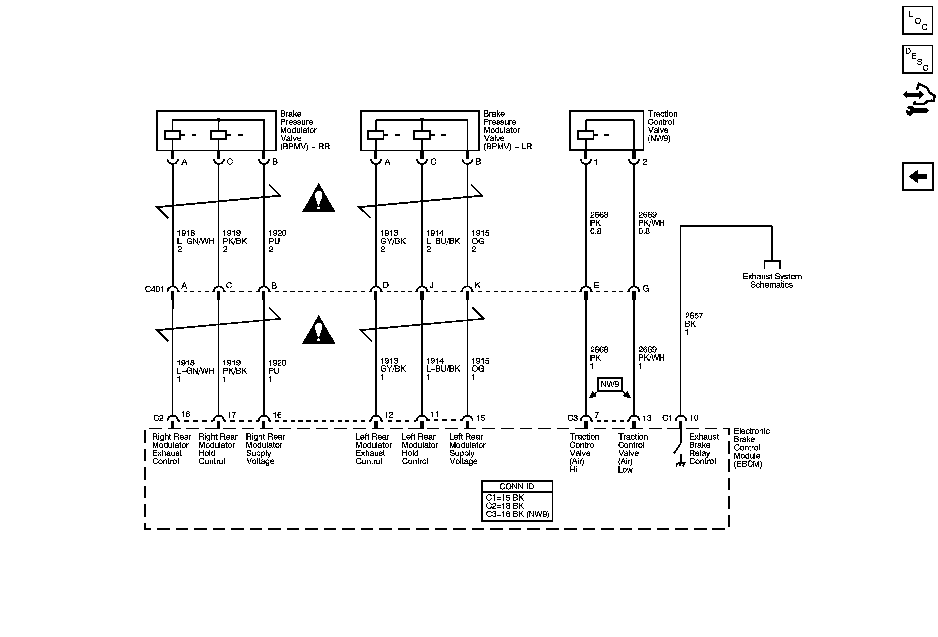
Figure
4:
BPMV
Master Electrical Component List
Air ABS Description and Operation
Control Module References
BPMV and WSS
Air Antilock Brake System Schematic Icons
Exhaust System Schematics