Removal Procedure
Notice: Cap the fittings and plug the holes when servicing the fuel system in order to prevent dirt and other contaminants from entering the open pipes and passages.
Important: Always maintain cleanliness when servicing fuel system components.
- Relieve the fuel pressure from the fuel system. Refer to Fuel Pressure Relief
- Clean the fuel rail assembly and connections.
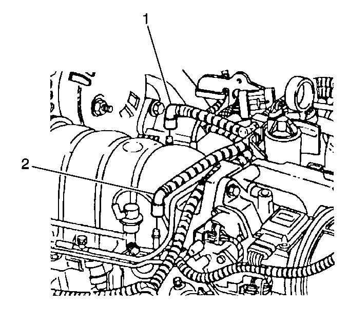
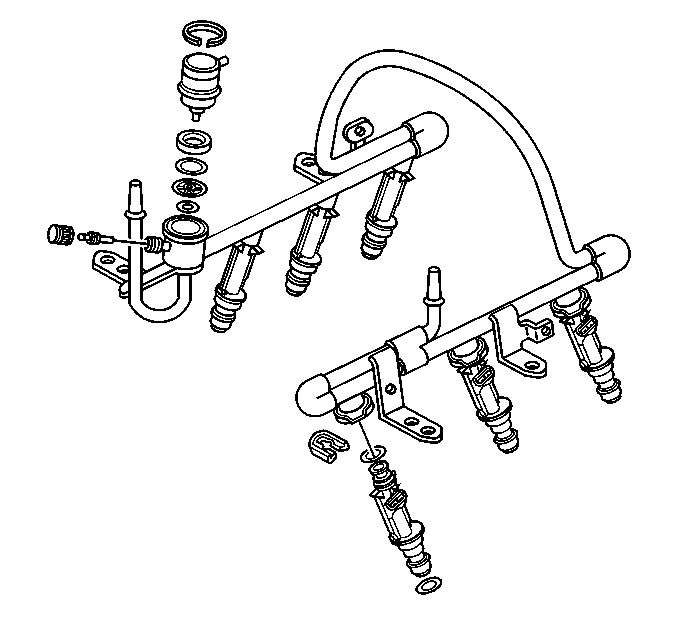
- Disconnect the fuel feed pipe, (1) and return pipe (2) from the fuel rail. Refer to Plastic Collar Quick Connect Fitting Service .
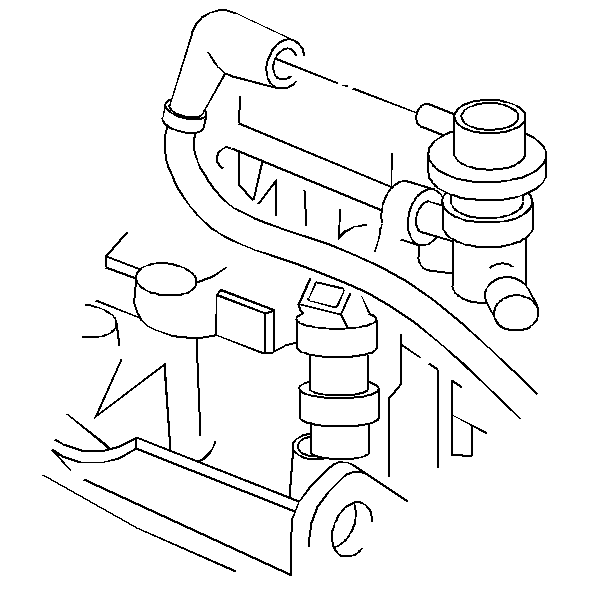
- Disconnect the vacuum line from the fuel pressure regulator.
- Disconnect the rear bank spark plug wires. Refer to Spark Plug Wire Replacement .
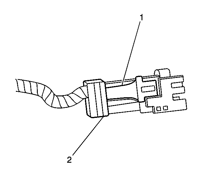
- Pull up the lock release (2) on the fuel injector connectors.
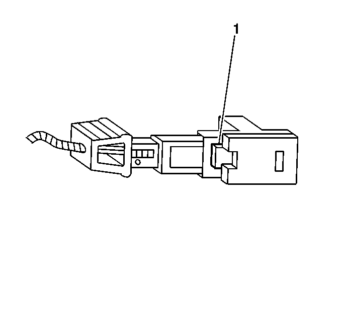
- Depress the lock tab (1) and lift the connector from the fuel injectors.
- Disconnect the ignition control module harness connector at the fuel rail.
- Remove the fuel rail hold-down nuts.
- Remove the fuel rail with equal force on both sides of the fuel rail.
Installation Procedure
Notice:
• Use care when servicing the fuel system components, especially
the fuel injector electrical connectors, the fuel injector tips, and
the injector O-rings. Plug the inlet and the outlet ports of the fuel rail
in order to prevent contamination. • Do not use compressed air to clean the fuel rail assembly as this
may damage the fuel rail components. • Do not immerse the fuel rail assembly in a solvent bath in order
to prevent damage to the fuel rail assembly.
- The O-rings must be replaced on all components that are serviced.
- Lightly oil the fuel injector O-rings with clean engine oil.
- Place the fuel rail assembly on the intake manifold.
- Seat the fuel injectors by HAND.
- Install the fuel rail hold down nuts.
- Connect the (6) fuel injector electrical connectors (1) to the fuel injectors.
- Push down the lock release lever (2) until it locks.
- Connect the ignition control module harness connector to the fuel rail.
- Connect the fuel feed (1) and return (2) pipes to the fuel rail. Refer to Plastic Collar Quick Connect Fitting Service .
- Connect the vacuum line to the fuel pressure regulator.
- Install the rear bank spark plug wires. Refer to Spark Plug Wire Replacement .
- Connect the negative battery cable. Refer to Battery Negative Cable Disconnection and Connection in Engine Electrical.
- Inspect for leaks.
- Install the fuel injection sight shield. Refer to Fuel Injector Sight Shield Replacement in Engine Mechanical.
Notice: Use the correct fastener in the correct location. Replacement fasteners must be the correct part number for that application. Fasteners requiring replacement or fasteners requiring the use of thread locking compound or sealant are identified in the service procedure. Do not use paints, lubricants, or corrosion inhibitors on fasteners or fastener joint surfaces unless specified. These coatings affect fastener torque and joint clamping force and may damage the fastener. Use the correct tightening sequence and specifications when installing fasteners in order to avoid damage to parts and systems.
Tighten
Tighten the fuel rail hold-down nuts to 10 N·m (89 lb ft).


| 13.1. | Turn ON the ignition for 2 seconds. |
| 13.2. | Turn OFF the ignition for 10 seconds. |
| 13.3. | Turn ON the ignition. |
| 13.4. | Inspect for fuel leaks. |
