GM Service Manual Online
For 1990-2009 cars only
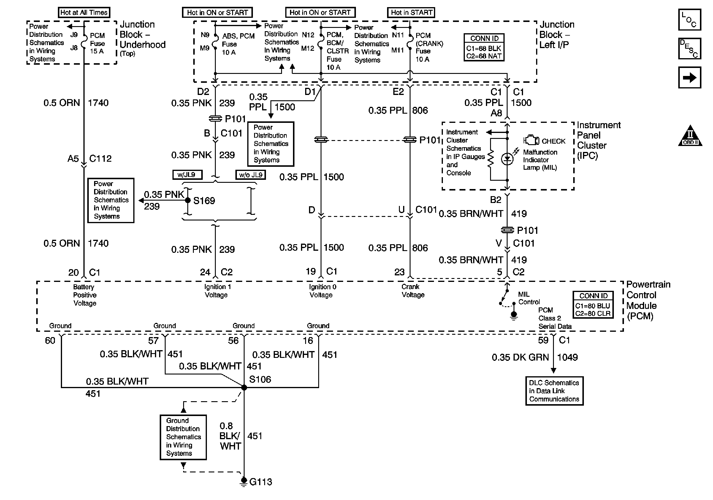
Figure 1:

Data Link, Grounds, MIL, and Power


Object Number: 669514  Size: FS
Master Electrical Component List
Powertrain Control Module Description
Ignition Control
Engine Controls Schematic Icons
A/C RLY (CMPR), DRL/EXT LTS, EXT LTS, FOG RLY, F/PMP RLY, HORN RLY, LEFT I/P, PCM, RT IP#1, RT IP#2, Spot Lamp, and U/HOOD#1 Fuses
ABS/PCM, SRS, STOP, and TURN SIGNAL Fuses
A/C/CRUISE, A/C FAN, CRUISE, PCM/BCM/CLSTR, and PCM (CRANK) Fuses
ABS/PCM, SRS, STOP, and TURN SIGNAL Fuses
A/C/CRUISE, A/C FAN, CRUISE, PCM/BCM/CLSTR, and PCM (CRANK) Fuses
Ground, Odometer/PRNDL, Power, and VSS
DLC Schematics
G113 (2 of 2)
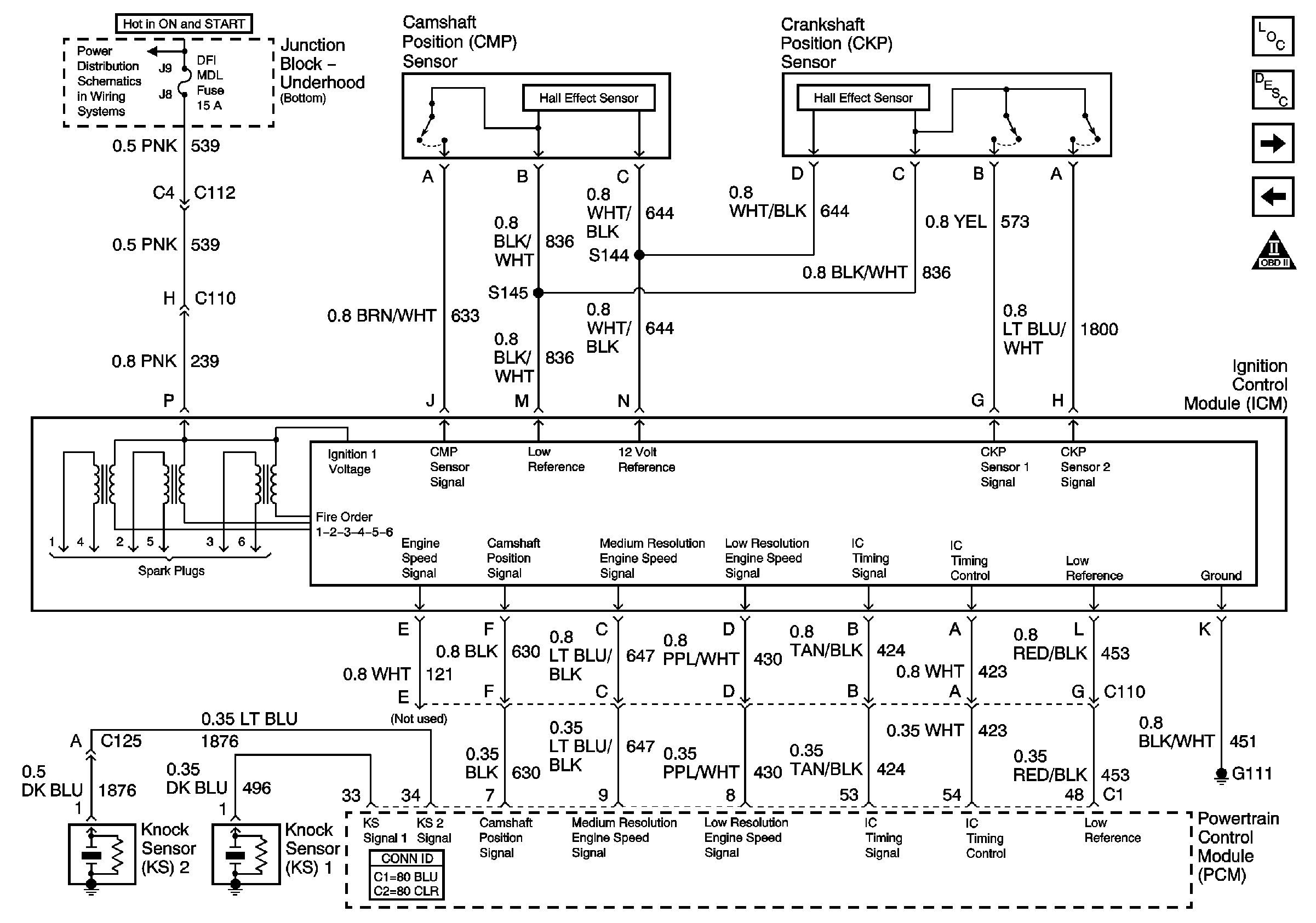
Figure 2:

Ignition Control


Object Number: 669517  Size: FS
Master Electrical Component List
Electronic Ignition (EI) System Description
Fuel Controls
Data Link, Grounds, MIL, and Power
Engine Controls Schematic Icons
DFI MDL, ENG DEVICES, and OXY SEN Fuses
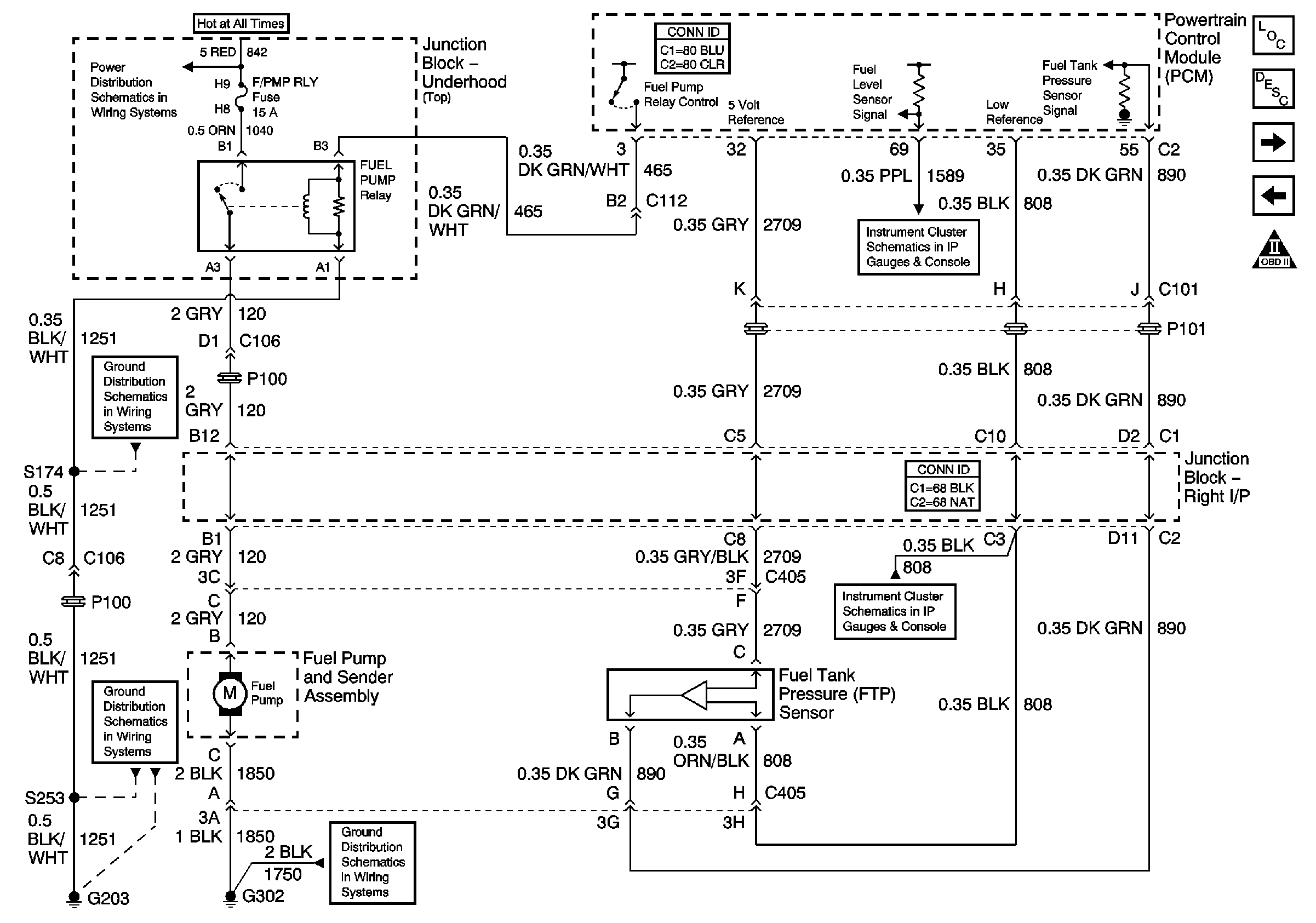
Figure 3:

Fuel Controls


Object Number: 669519  Size: FS
Master Electrical Component List
Fuel System Description
Fuel Injectors
Ignition Control
Engine Controls Schematic Icons
A/C RLY (CMPR), DRL/EXT LTS, EXT LTS, FOG RLY, F/PMP RLY, HORN RLY, LEFT I/P, PCM, RT IP#1, RT IP#2, Spot Lamp, and U/HOOD#1 Fuses
Gauges, Illumination, and Indicators
G302 (1 of 2)
G203 (1 of 3)
G203 (3 of 3)
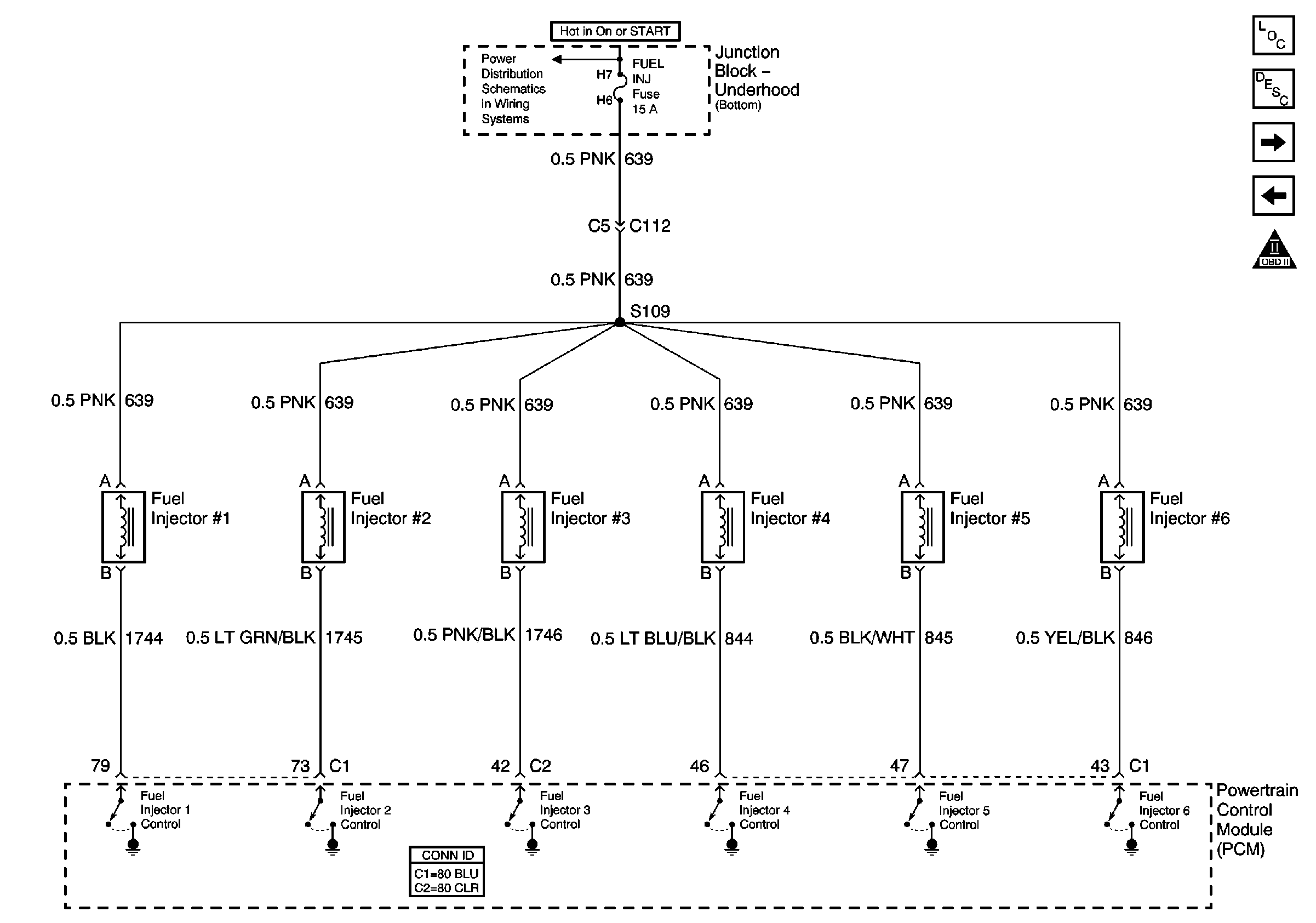
Figure 4:

Fuel Injectors


Object Number: 669521  Size: FS
Master Electrical Component List
Fuel System Description
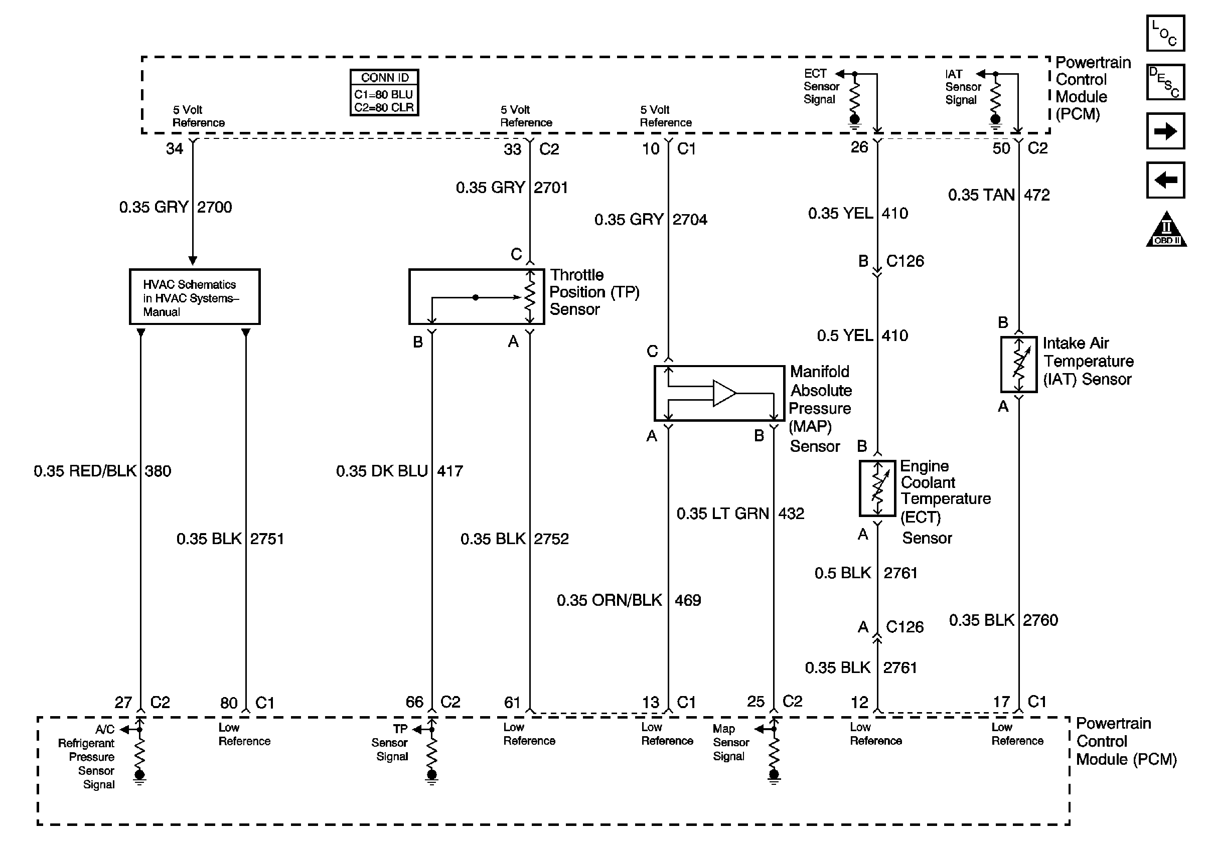
ECT, IAT, MAP, and TP Sensors, References to HVAC
Fuel Controls
Engine Controls Schematic Icons
FUEL INJ, and TRANS SOL Fuses
Figure 5:

ECT, IAT, MAP, and TP Sensors, References to HVAC


Object Number: 669522  Size: FS
Master Electrical Component List
Powertrain Control Module Description
HO2S and VSS
Fuel Injectors
Engine Controls Schematic Icons
Compressor Control
Figure 6:

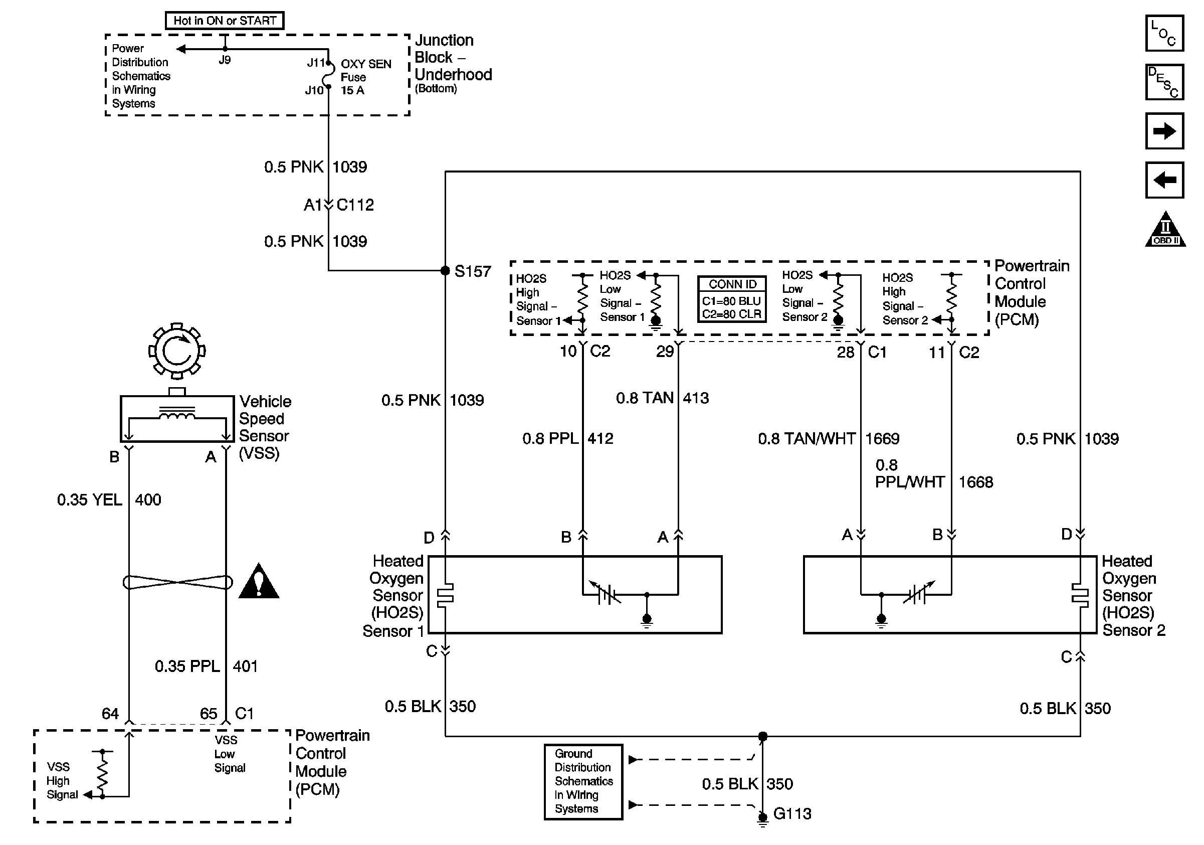
HO2S and VSS


Object Number: 669524  Size: FS
Master Electrical Component List
Powertrain Control Module Description
Air Injection, EVAP Purge, and MAF
ECT, IAT, MAP, and TP Sensors, References to HVAC
Engine Controls Schematic Icons
A/C RLY (COIL), AIR PMP RLY, COOLING FANS, DFI MDL, ENG DEVISES, FANCONT#1, FAN CONT#2&3, FUEL INJ, IGN SW, OXY SEN, RT IP#3, TRANS SOL, AND U/HOOD#2 Fuses
Engine Controls Schematic Icons
G100, G111, G113, G117, and G151 (1 of 2)
Figure 7:

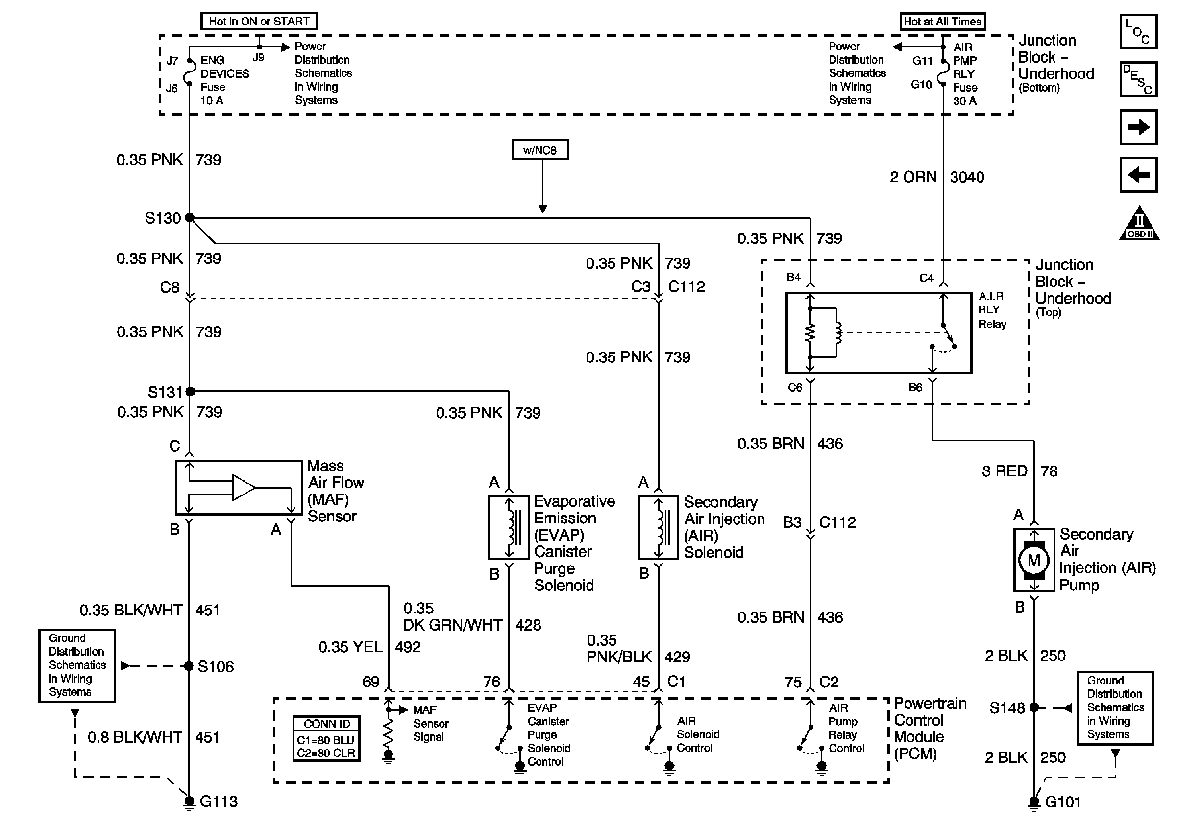
Air Injection, EVAP Purge, and MAF


Object Number: 669525  Size: FS
Master Electrical Component List
Secondary Air Injection System Description
EGR, EOP, IAC, and EVAP Vent
HO2S and VSS
Engine Controls Schematic Icons
DFI MDL, ENG DEVICES, and OXY SEN Fuses
G101
G113 (2 of 2)
Figure 8:

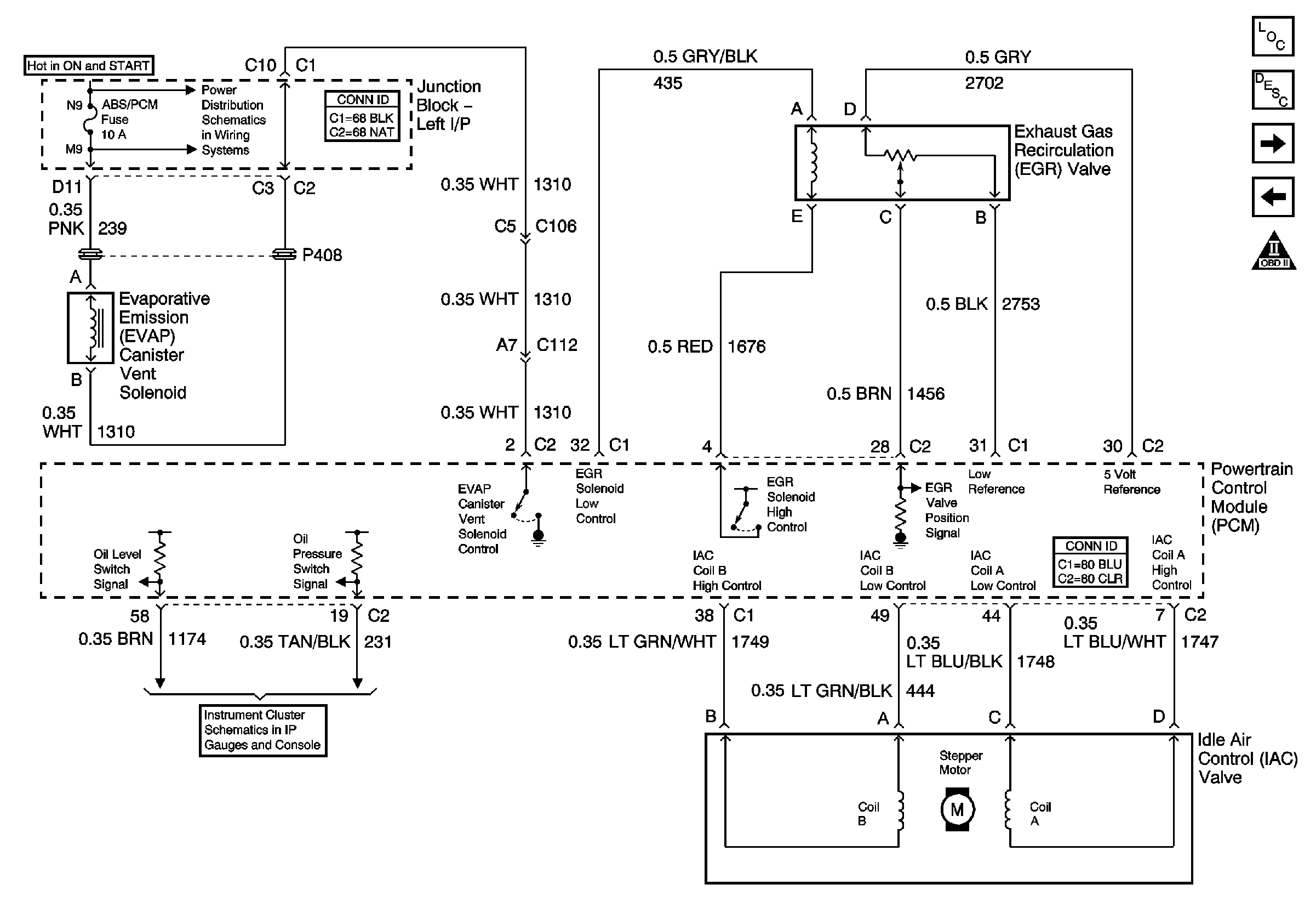
EGR, EOP, IAC, and EVAP Vent


Object Number: 669527  Size: FS
Master Electrical Component List
Powertrain Control Module Description
PCM References
Air Injection, EVAP Purge, and MAF
Engine Controls Schematic Icons
ABS/PCM, SRS, STOP, and TURN SIGNAL Fuses
Message Center
Figure 9:

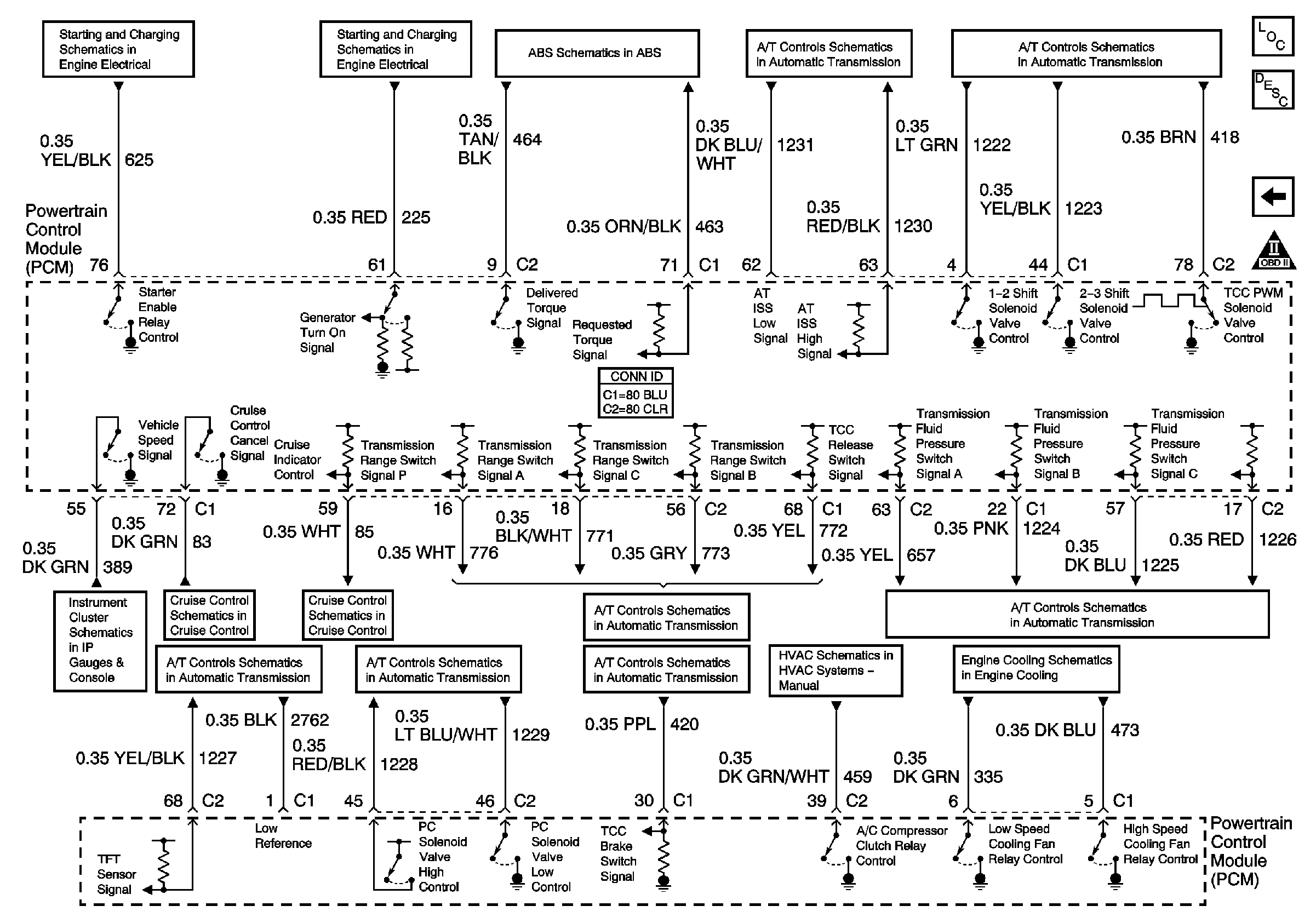
PCM References


Object Number: 669528  Size: FS
Master Electrical Component List
Powertrain Control Module Description
EGR, EOP, IAC, and EVAP Vent
Engine Controls Schematic Icons
Engine Cranking
Charging Control and Indicator
PCM and Stoplamps Switch
ISS, Pressure Control, Switches, and VSS
Solenoids, TCC, and TFT
ISS, Pressure Control, Switches, and VSS
PRNDL
Impala
Monte Carlo
Ground, Odometer/PRNDL, Power, and VSS
Solenoids, TCC, and TFT
ISS, Pressure Control, Switches, and VSS
Solenoids, TCC, and TFT
Compressor Control
1/1