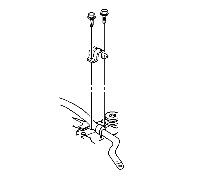
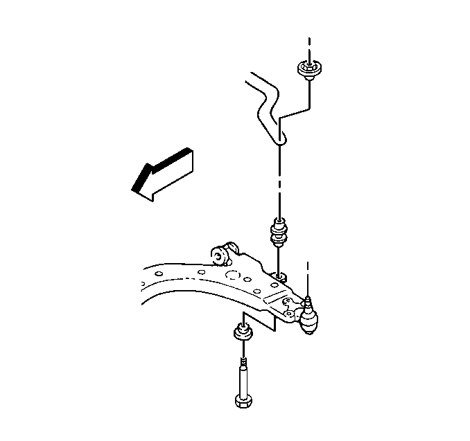
Removal Procedure
Caution: Failure to disconnect intermediate shaft from rack and pinion stub shaft can result in damage to steering gear and/or intermediate shaft. This damage can cause loss of steering control which could result in personal injury.
- Raise and suitably support the vehicle. Refer to Lifting and Jacking the Vehicle in General Information.
- Remove the tire and wheel assembly. Refer to Tire and Wheel Removal and Installation in Tires and Wheels.
- Move the steering shaft dust seal in order to gain access to the pinch bolt.
- Remove the pinch bolt from the lower intermediate steering shaft. Refer to Intermediate Steering Shaft Replacement in Steering Wheel And Column-Tilt.
- Remove all insulator clamp attaching bolts.
- Place a jackstand under the center of the rear frame crossmember.
- Loosen the front frame bolts.
- Remove the rear frame bolts.
- Lower the rear of the frame just enough to gain access to the stabilizer shaft.
- Remove the bolts and the clamps from the frame. Refer to Frame Replacement in Frame and Underbody.
- Remove the insulators from the stabilizer bar.
- Remove the stabilizer bar links from the control arms.
- Pull the stabilizer shaft rearward.
- Swing the stabilizer shaft down to remove the stabilizer shaft from the left side of the vehicle.


Installation Procedure
Caution: When installing the intermediate shaft make sure that the shaft is seated prior to pinch bolt installation. If the pinch bolt is inserted into the coupling before shaft installation, the two mating shafts may disengage. Disengagement of the two mating shafts will cause loss of steering control which could result in personal injury.
- Insert the stabilizer shaft to the left side of the vehicle.
- Loosely install the stabilizer shaft link at the control arm.
- Install the insulators from the stabilizer bar.
- Connect the insulator clamps to the frame.
- Raise the frame into position while you guide the steering shaft onto the gear.
- Install the new frame-to-body attaching bolts. Refer to Frame Replacement in Frame and Underbody.
- Remove the jackstand.
- Install the pinch bolt and tighten. Refer to Intermediate Steering Shaft Replacement in Steering Wheel And Column-Tilt.
- Install the dust seal into the steering gear.
- Support the weight of the vehicle by the control arms.
- Tighten the stabilizer link nut.
- Install the tire and wheel assembly. Refer to Tire and Wheel Removal and Installation in Tires and Wheels.
- Lower the vehicle.

Important: DO NOT tighten the stabilizer link nut at this time. The weight of the vehicle must be supported by the control arms such that you can obtain the vehicle design trim heights before tightening the link nut.


Notice: Use the correct fastener in the correct location. Replacement fasteners must be the correct part number for that application. Fasteners requiring replacement or fasteners requiring the use of thread locking compound or sealant are identified in the service procedure. Do not use paints, lubricants, or corrosion inhibitors on fasteners or fastener joint surfaces unless specified. These coatings affect fastener torque and joint clamping force and may damage the fastener. Use the correct tightening sequence and specifications when installing fasteners in order to avoid damage to parts and systems.
Tighten
Tighten the stabilizer shaft bracket bolts to 48 N·m (35 lb ft).
Tighten
Tighten the stabilizer shaft link nut to 23 N·m (17 lb ft).
