For 1990-2009 cars only
Control Arm Bushing Replacement Suspension Insulator
Tools Required
J 44570 Bushing Remover/Installer Kit
Removal Procedure
- Raise and support the vehicle. Refer to Lifting and Jacking the Vehicle .
- Remove the rear wheels. Refer to Tire and Wheel Removal and Installation .
- Place 2 screw type jack stands under both ends of the rear axle.
- Remove the rear brake hose bracket attaching nuts from the body.
- Detach the rear brake hose brackets from the body allowing the lines to hang free.
- Remove the lower shock bolts.
- Lower the jacks in order to remove the coil springs.
- Temporarily re-install the lower shock bolts to support the axle.
- Remove the bushing bracket to body bolts from both ends of the rear axle.
- Using the jack stands, raise the rear of the axle until the bushing brackets pivot away from the body.
- Remove the axle bushing through bolts and remove the bushing brackets.
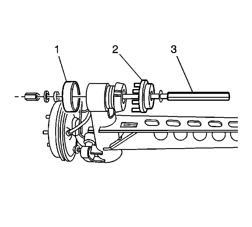
- Using the J 44570 , install the J 44570-1 (2) with the lip between the axle sleeve and bushing flange. It may require tapping with a hammer to fully seat the tool.
- Insert J 44570-3 (1) through the J 44570-1 (2) and the axle bushing.
- Install the washer and nut by hand, tightening until the tool is snug.
- Using a hammer, drive the bushing from the axle sleeve.
- Disassemble the tool and remove the bushing.
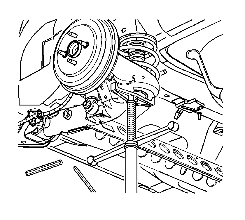
Important: Do not kink the brake pipes while lowering the axle.
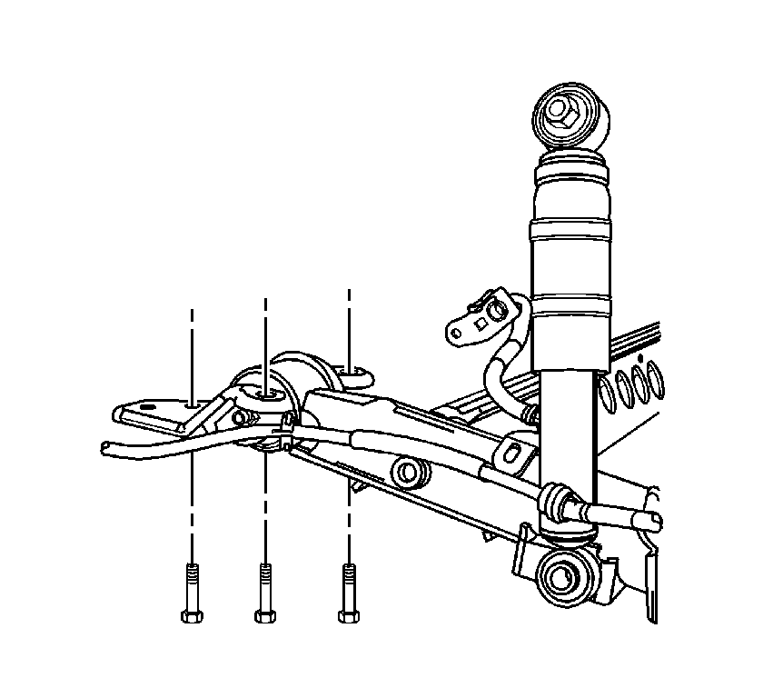
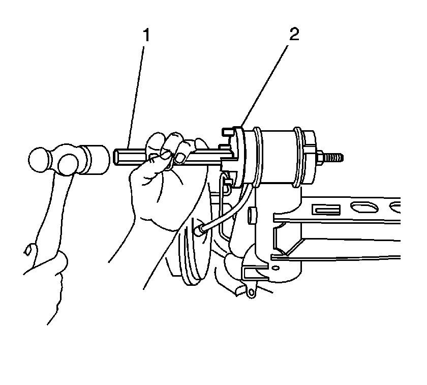
Important: Note the depth and orientation of the old bushing before removal.
Installation Procedure
- Slide the new bushings into the axle sleeve in the same orientation noted during removal. Make sure the rubber end (1) is facing inboard and the largest void (2) is in line with the wheel hub center (3).
- Place the J 44570-1 (2) onto the bushing. Make sure the bushing is still oriented correctly.
- Insert the J 44570-3 (3) through the J 44570-1 (2) and the axle bushing.
- Install the J 44570-2 (1) bearing, washer, and nut.
- Pull the bushing into the axle sleeve by holding the hex end of the threaded shaft while turning the nut.
- Disassemble and remove the bushing installation tool from the axle.
- Install the axle brackets to the axle bushings with the alignment slot on the outboard side.
- Loosely install the bushing bolts, park brake cable brackets and nuts .
- Using the jack stands, lower the rear of the axle until the bushing brackets contact the body.
- Hand tighten the axle bracket to body bolts just enough to hold the brackets flush to the body.
- Using the jack stands, raise the axle to the proper trim height specification by measuring the vertical distance between the bottom edge of the upper spring seat and the bottom of the notch in the lower spring seat. Refer to Trim Height Inspection for D Height Measurement.
- Tighten the axle bushing through bolts.
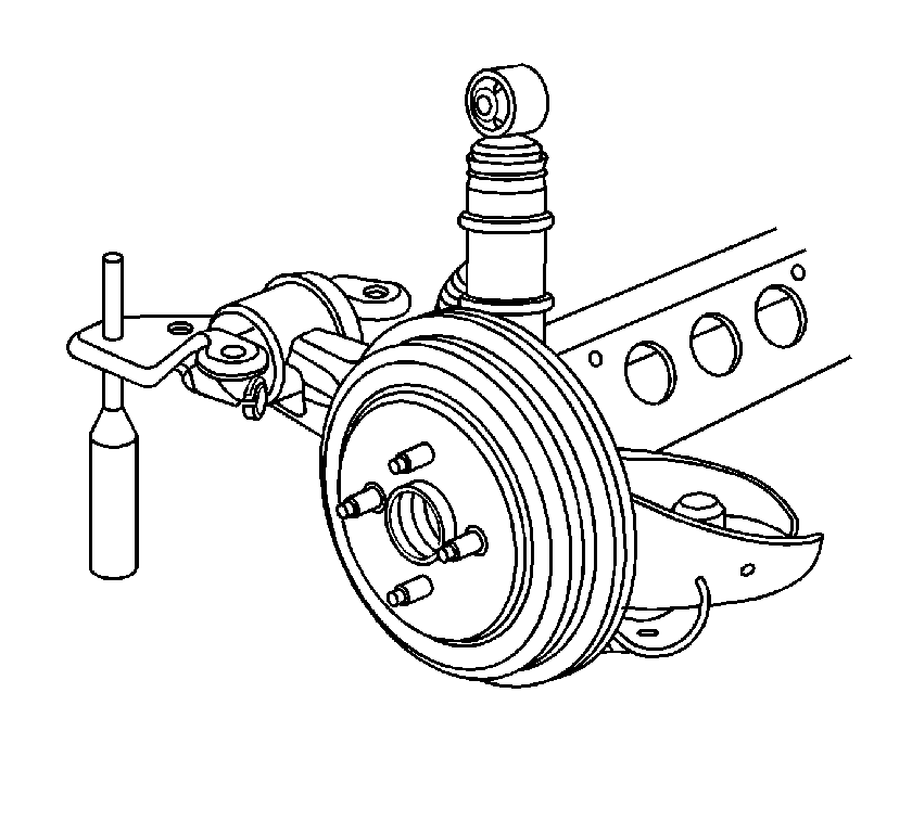
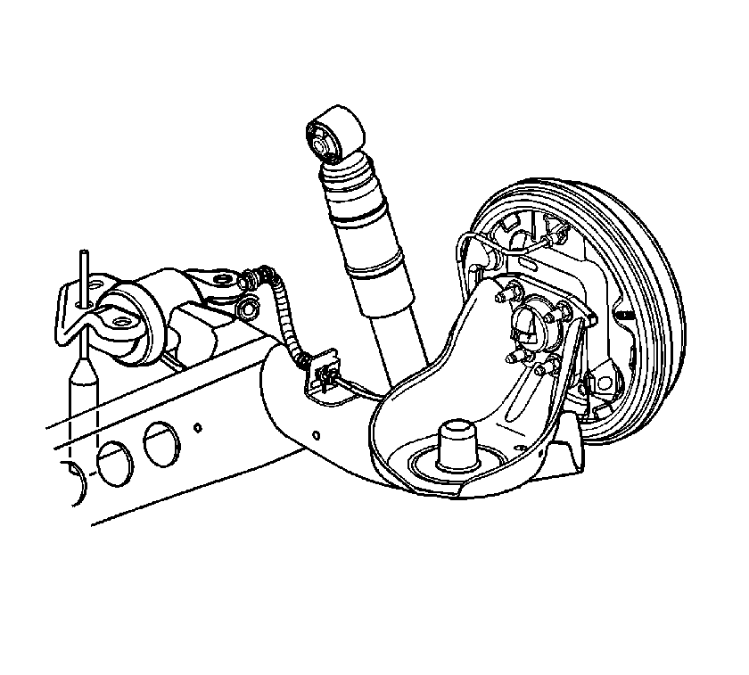
- Insert two 12 mm diameter pins through the axle brackets into the underbody.
- Align the left side axle bracket and snug down the bolts.
- Align the right side axle bracket and snug down the bolts.
- Tighten all the bracket to body bolts.
- With the axle supported by the jack stands, remove the lower shock bolts.
- Lower the jacks in order to install the coil springs.
- Install the coil springs, making sure the colored tag is facing the rear of the vehicle.
- Raise the jacks until the springs are slightly compressed in order to install the lower shock bolts. Refer to Shock Absorber Replacement .
- Remove the jack stands.
- Reposition the rear brake hose brackets to the body.
- Install the brake hose bracket attaching nuts.
- Install the rear wheels. Refer to Tire and Wheel Removal and Installation .
- Lower the vehicle.
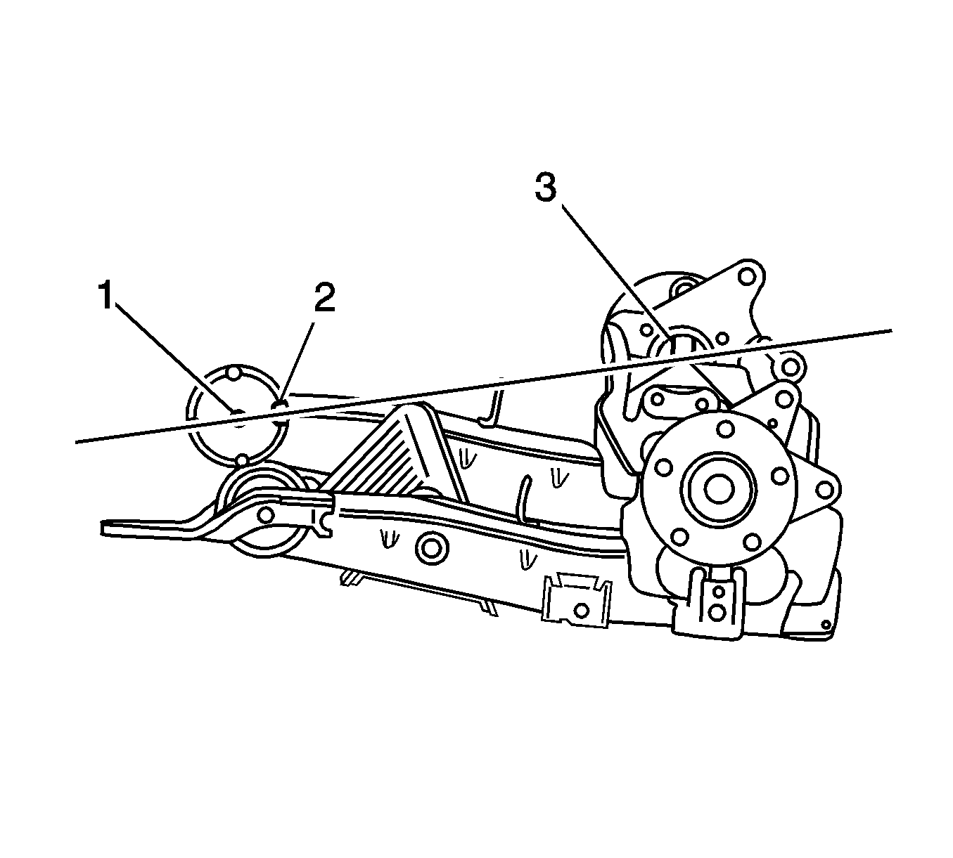
Important: The axle bushings must be installed in the correct orientation as shown.
Important: The axle bushing through bolts must be installed with the bolt head facing inboard.

Important: The axle through bolts must be tightened with the axle at the correct trim height and prior to torquing the axle bracket to body bolts.
Notice: Refer to Fastener Notice in the Preface section.
Tighten
Tighten the bolts to 90 N·m (66 lb ft) plus 60 degrees
Tighten
Tighten the bolts to 90 N·m (66 lb ft) plus 30 degrees.
Tighten
Tighten the lower bolts to 125 N·m (92 lb ft).
