GM Service Manual Online
For 1990-2009 cars only
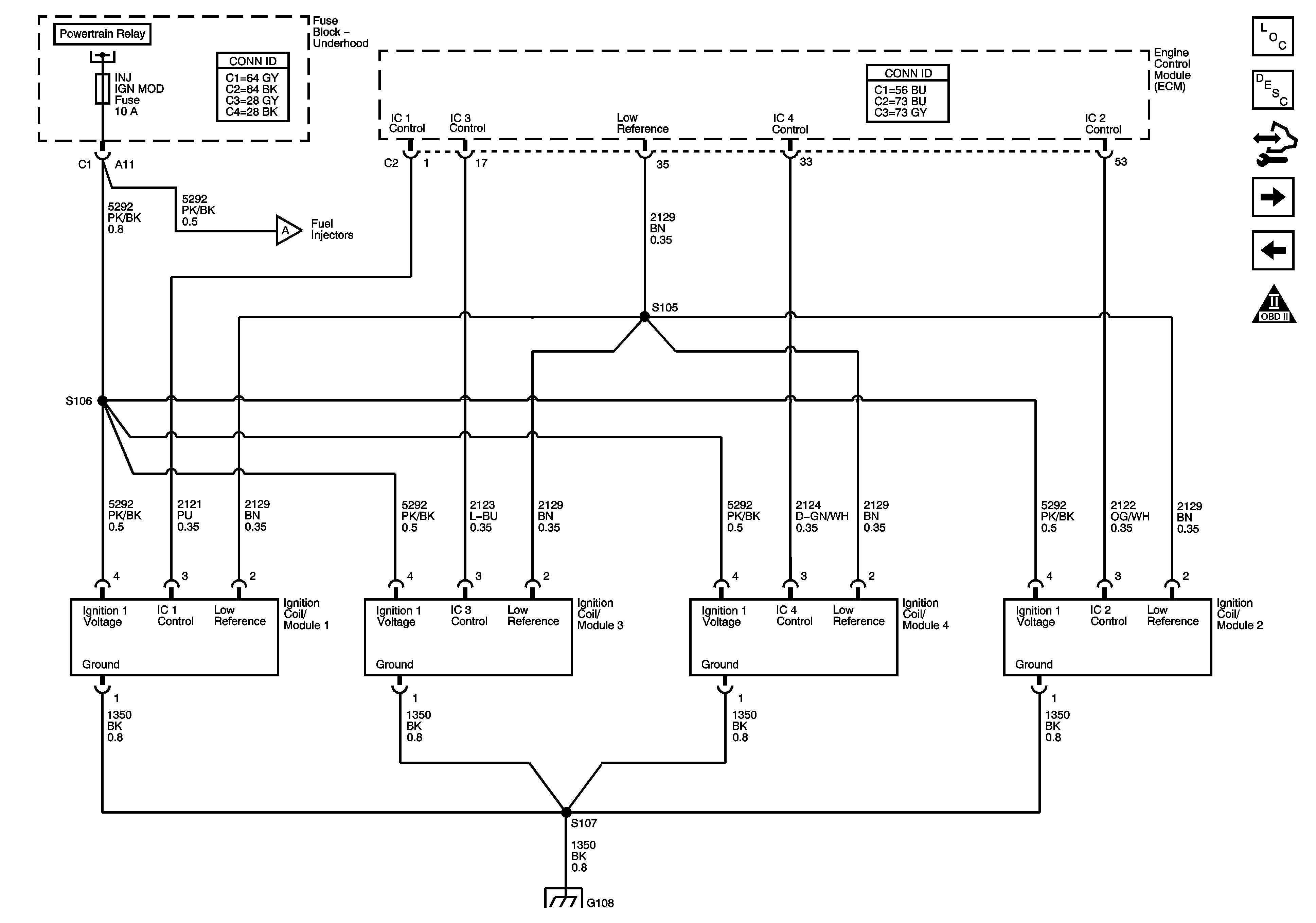
Figure 1:

Power, Ground, MIL, and DLC


Object Number: 1570570  Size: FS
Master Electrical Component List
Engine Control Module Description
Control Module References
Engine Data Sensors - 5-Volt and Low Reference
Engine Controls Schematic Icons
Underhood Fuse Block - B+ Bus
Body Control Module - BCM 2, HVAC / PK3, CLUSTER, IGN SW, STOP LPS, and AMP Fuses
High Speed GMLAN
Body Control Module - BCM 2, HVAC / PK3, CLUSTER, IGN SW, STOP LPS, and AMP Fuses
TCM Power and Ground
Underhood Fuse Block - B+ Bus
G109
G103, G105, G017, and G108
G109
Body Control Module - RAP, DRIVERS DOOR UNLOCK PCB, DOOR UNLOCK PCB, DOOR LOCK PCB and INTERIOR LAMPS PCB Relays, RDO, PWR WINDW, DR LCK, INT LIGHT, ECM / TCM, SDM, S ROOF and SPARE Fuses
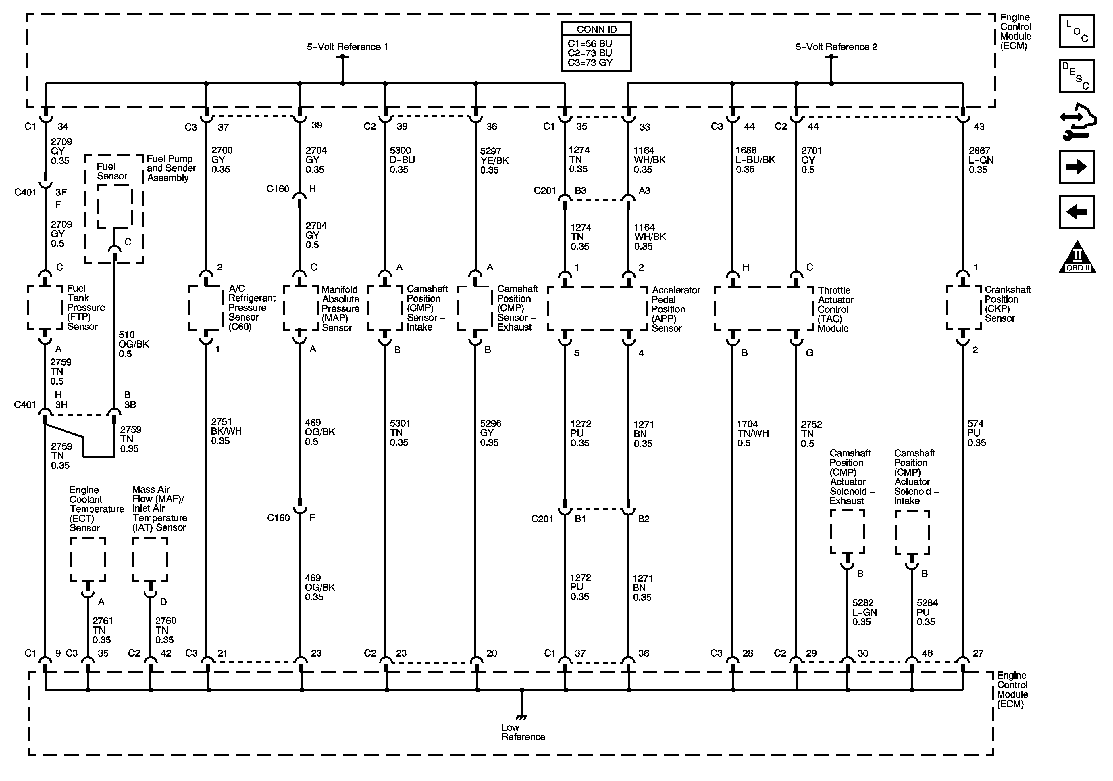
Figure 2:

Engine Data Sensors - 5-Volt and Low References

Object Number: 1570572  Size: FS
Master Electrical Component List
Engine Control Module Description
Control Module References
Engine Data Sensors - Pressure, Temp, and MAF/IAT
Power, Ground, MIL, and DLC
Engine Controls Schematic Icons
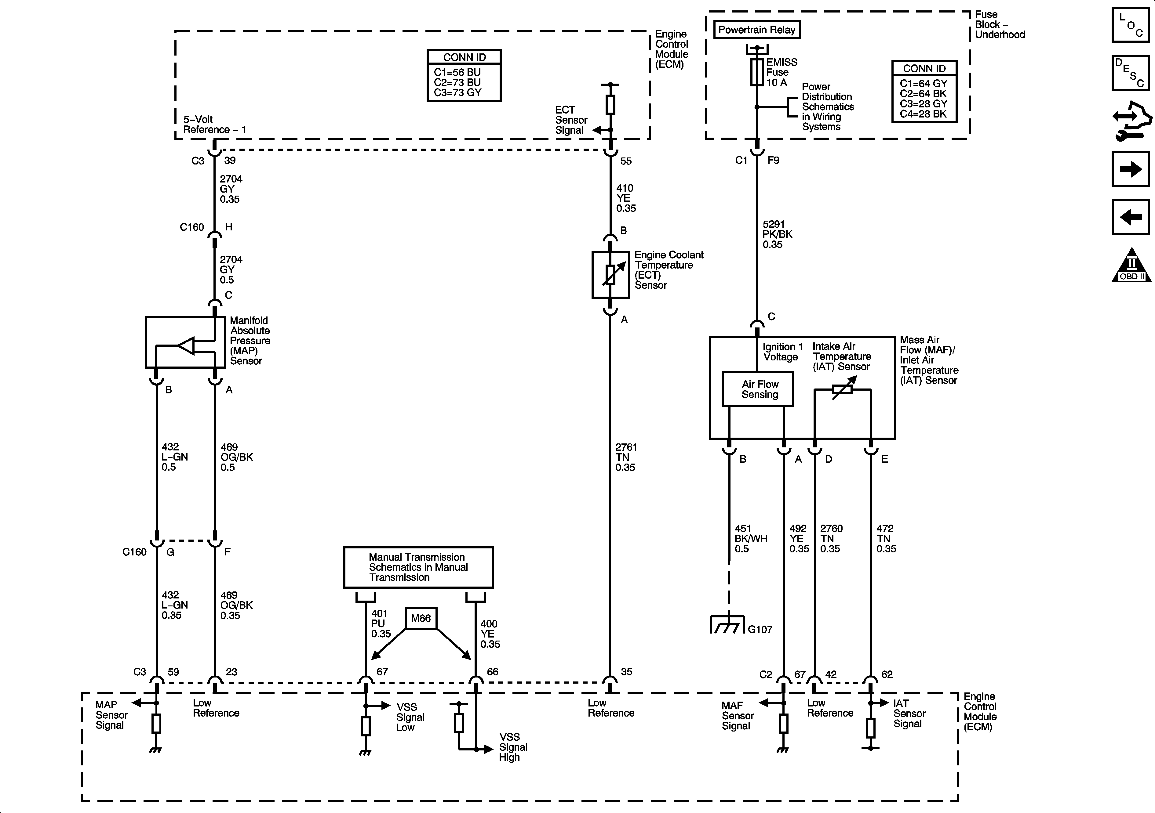
Figure 3:

Engine Data Sensors - Pressure, Temp, and MAF/IAT


Object Number: 1570576  Size: FS
Master Electrical Component List
Engine Control Module Description
Control Module References
Engine Data Sensors - H2OS
Engine Data Sensors - 5-Volt and Low Reference
Engine Controls Schematic Icons
Manual Transmission
Underhood Fuse Block - LIFTGATE RELEASE, POWERTRAIN Relay, LIFTGATE / SUNROOF, EMISSION, INJ IGN MOD and ECM Fuses
G103, G105, G017, and G108
Figure 4:

Engine Data Sensors - HO2S


Object Number: 1570578  Size: FS
Master Electrical Component List
Engine Control Module Description
Control Module References
Engine Data Sensors - APP and TAC
Engine Data Sensors - Pressure, Temp, and MAF/IAT
Engine Controls Schematic Icons
Underhood Fuse Block - LIFTGATE RELEASE, POWERTRAIN Relay, LIFTGATE / SUNROOF, EMISSION, INJ IGN MOD and ECM Fuses
Figure 5:

Engine Data Sensors - APP and TAC


Object Number: 1570581  Size: FS
Master Electrical Component List
Throttle Actuator Control (TAC) System Description
Control Module References
Ignition Controls - Ignition System
Engine Data Sensors - H2OS
Engine Controls Schematic Icons
Figure 6:

Ignition System


Object Number: 1570584  Size: FS
Master Electrical Component List
Electronic Ignition (EI) System Description
Control Module References
Ignition Controls - Sensors
Engine Data Sensors - APP and TAC
Engine Controls Schematic Icons
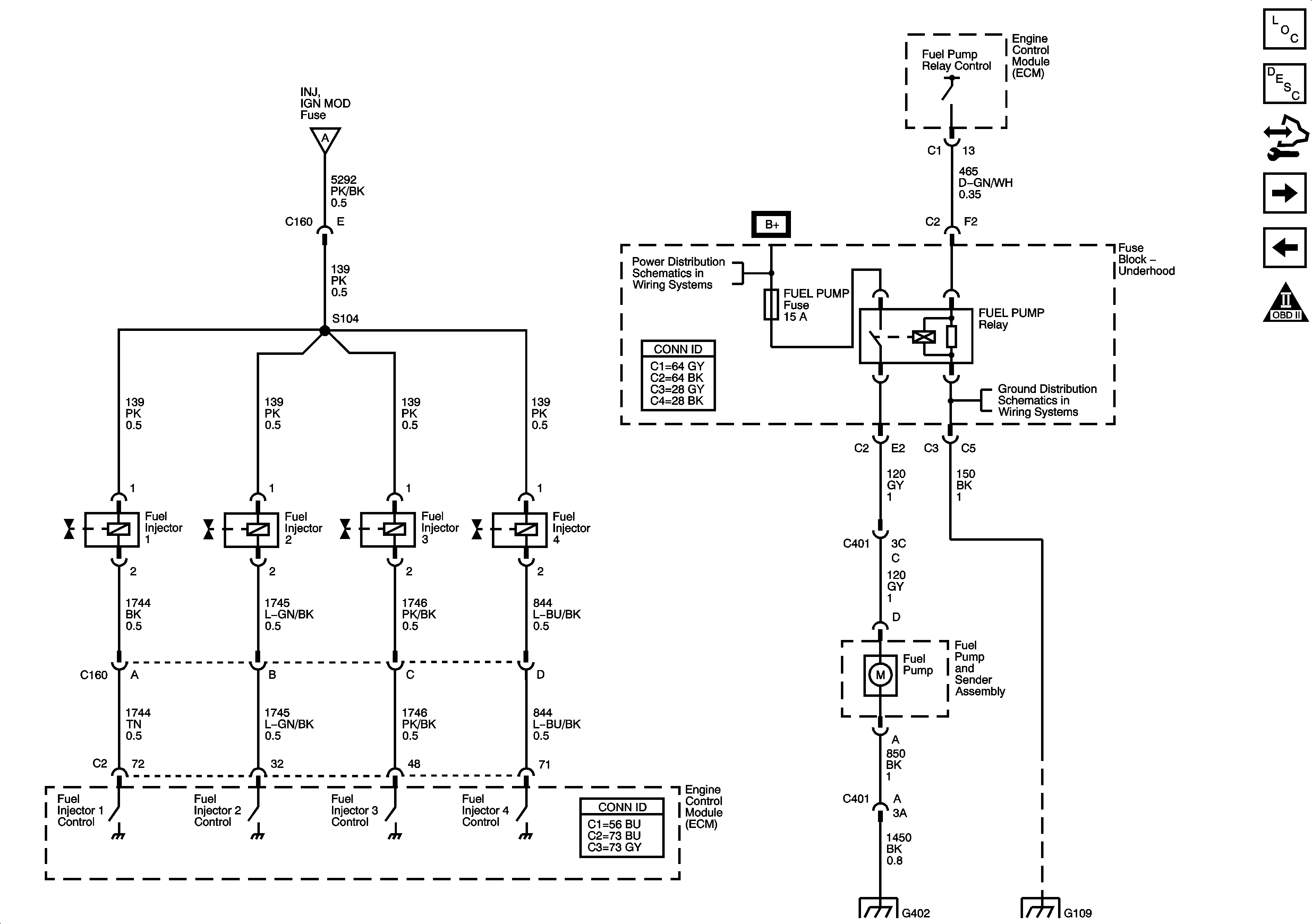
Fuel Controls
G103, G105, G017, and G108
Figure 7:

Ignition Controls - Sensors


Object Number: 1570586  Size: FS
Master Electrical Component List
Engine Control Module Description
Control Module References
Fuel Controls
Ignition Controls - Ignition System
Engine Controls Schematic Icons
Figure 8:

Fuel Controls


Object Number: 1570588  Size: FS
Master Electrical Component List
Engine Control Module Description
Control Module References
EVAP Controls
Ignition Controls - Sensors
Engine Controls Schematic Icons
Ignition Controls - Ignition System
Underhood Fuse Block - B+ Bus
G109
G402
G109
Figure 9:

EVAP Controls


Object Number: 1570591  Size: FS
Master Electrical Component List
Evaporative Emission Control System Description
Control Module References
Controlled/Monitored Subsystem References
Fuel Controls
Engine Controls Schematic Icons
Ambient Air Temperature Sensor, EOP Sensor, Fuel Level Sensor, and Indicators
Underhood Fuse Block - ABS (20A), CNSTR VENT, PWR OUTLET and MIR Fuses, PWR SEATS Circuit Breaker
Underhood Fuse Block - LIFTGATE RELEASE, POWERTRAIN Relay, LIFTGATE / SUNROOF, EMISSION, INJ IGN MOD and ECM Fuses
Figure 10:

Controlled/Monitored Subsystem References


Object Number: 1570592  Size: FS
Master Electrical Component List
Engine Control Module Description
Control Module References
EVAP Controls
Engine Controls Schematic Icons
Ambient Air Temperature Sensor, EOP Sensor, Fuel Level Sensor, and Indicators
Manual Transmission
Clutch Pedal Position Switch and Stop Lamp Switch
Engine Cooling
Compressor Controls
Charging
Starting and Charging Schematics