For 1990-2009 cars only
Removal Procedure
- Remove the left side instrument panel insulator panel. Refer to Instrument Panel Insulator Panel Replacement - Left Side.
- Remove the communication interface module, if equipped. Refer to Communication Interface Module Replacement.
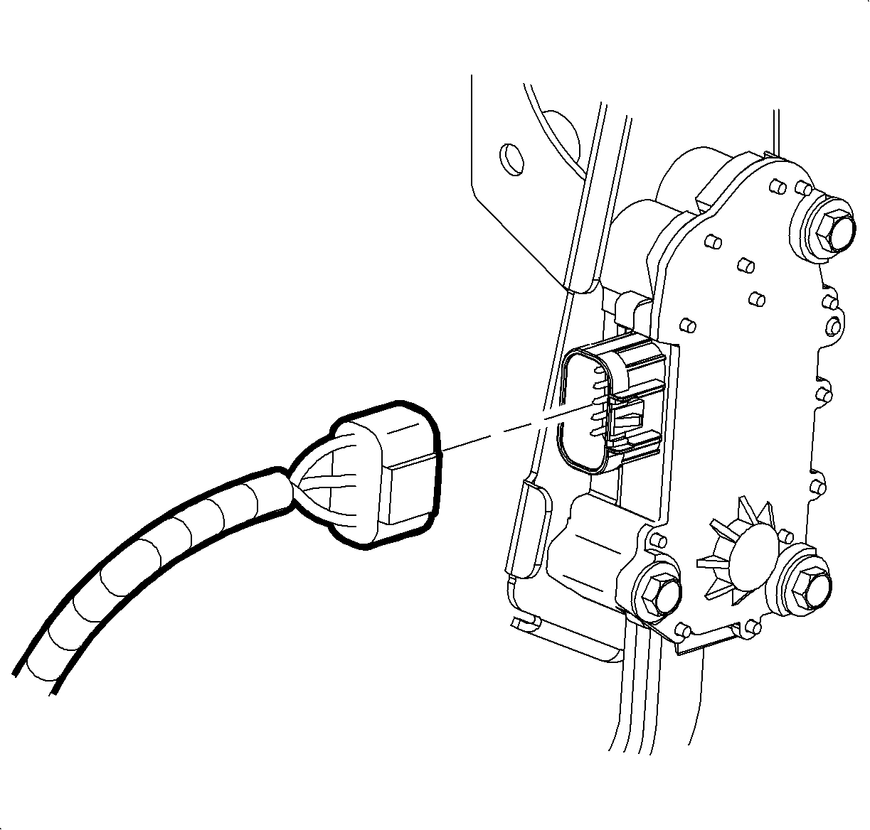
- Disconnect the accelerator pedal assembly electrical connector.
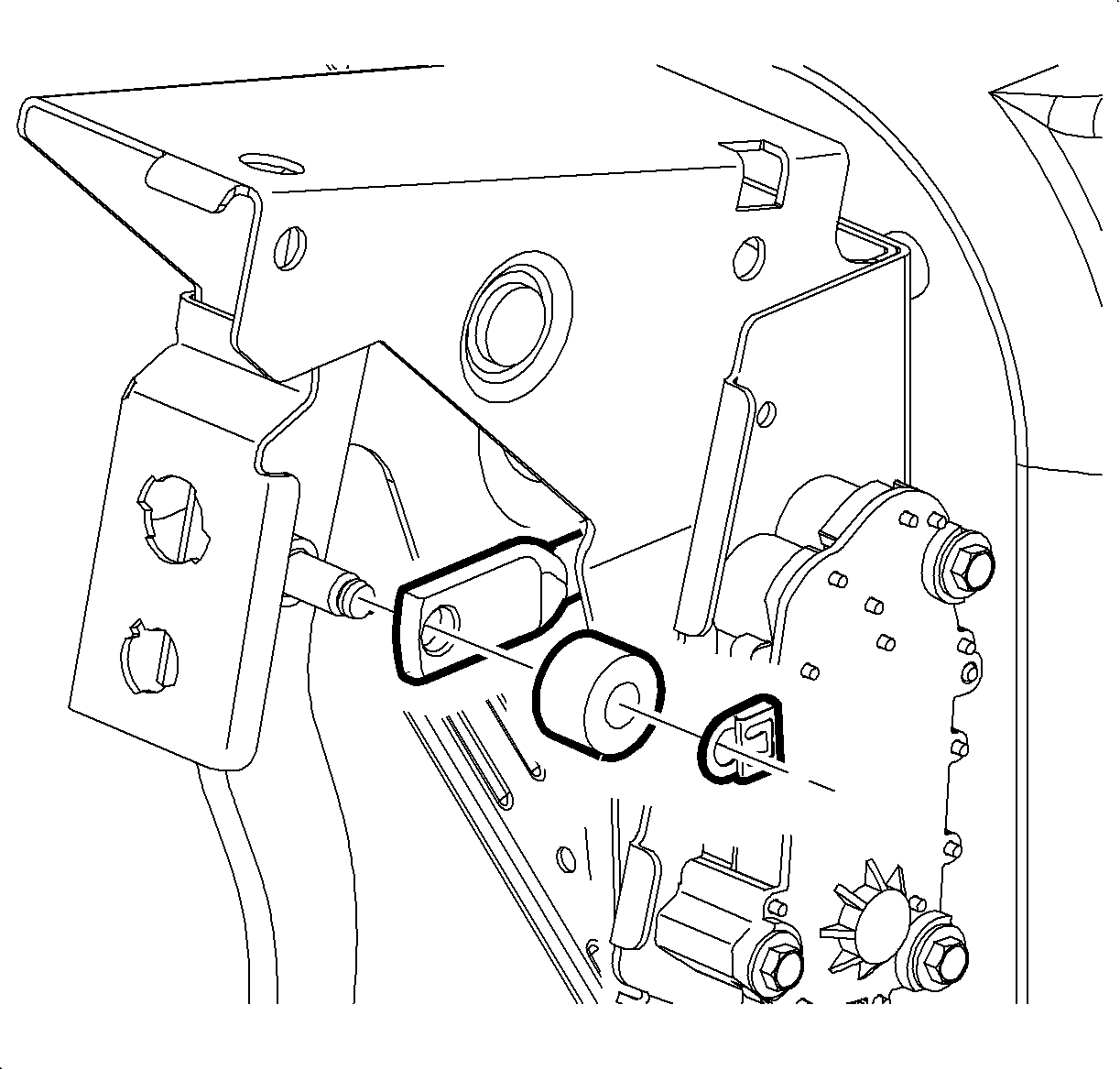
- Remove the retaining clip and washer from the brake pedal.
- Release the brake booster pushrod from the brake pedal.
- Disconnect the brake pedal position sensor electrical connector.
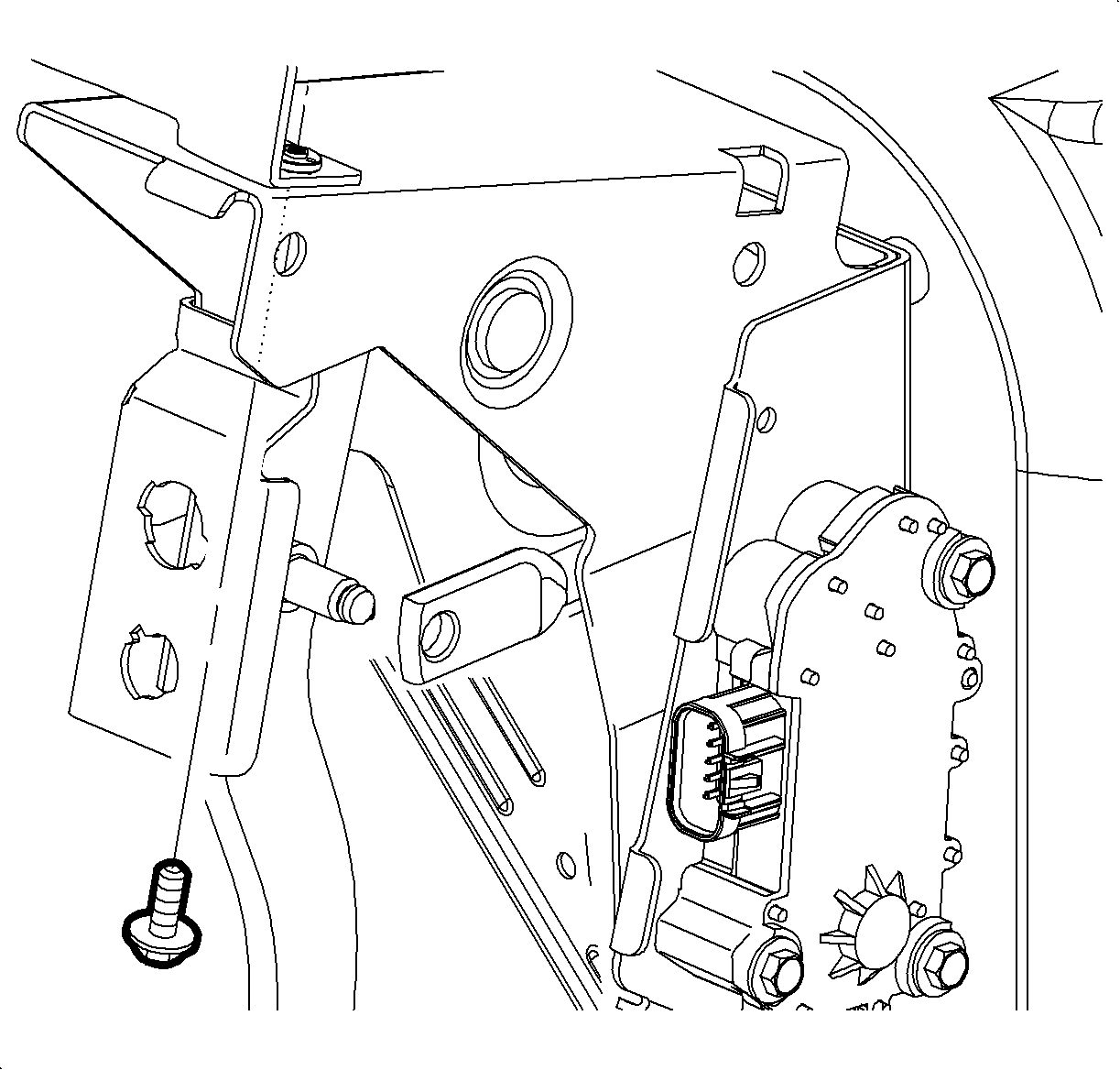
- Remove the brake pedal bracket-to-steering column bracket bolt.
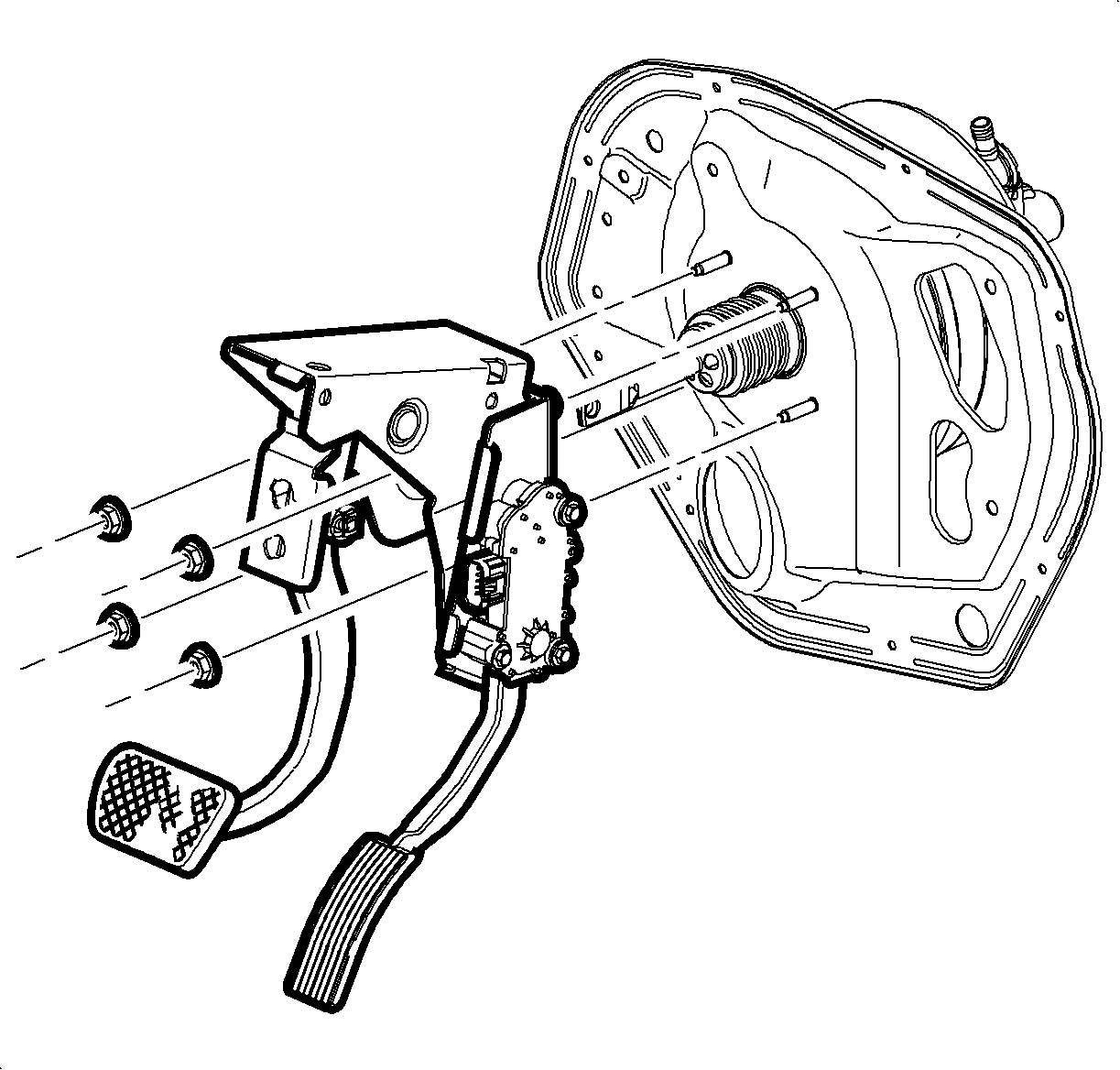
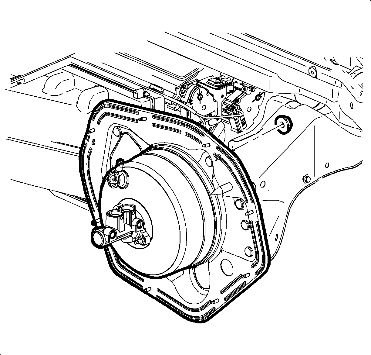
- Remove the brake booster mounting nuts.
- Position the brake booster forward to clear the studs from the front of the dash.
- Loosen, but do not remove, the steering column bracket to cowl nut.
- While simultaneously disengaging the brake pedal bracket pilot bushings from the foam insulation panel, pull the brake pedal assembly back and toward the center of the vehicle.
- Remove the brake pedal assembly from the vehicle.
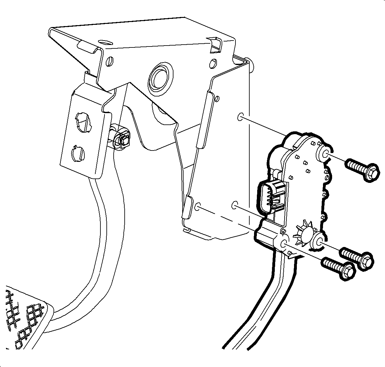
- Remove the accelerator pedal assembly from the brake pedal bracket. Refer to Accelerator Pedal Position Sensor Replacement.
Installation Procedure
- Install the accelerator pedal assembly to the brake pedal bracket. Refer to Accelerator Pedal Position Sensor Replacement.
- Install the brake pedal assembly into the vehicle, while guiding the brake pedal bracket pilot bushings into the foam insulator panel.
- Position the booster studs through dash panel.
- Install the brake pedal bracket-to-steering column bracket bolt.
- Loosely install the brake booster mounting nuts.
- Apply a thin coating of lithium grease to the pushrod pin on the brake pedal.
- Connect the brake booster pushrod to the brake pedal.
- Install the washer and retaining clip to the brake pedal.
- Tighten the vacuum brake booster mounting nuts.
- Install the steering column bracket to cowl nut.
- Connect the brake pedal position sensor electrical connector.
- Connect the accelerator pedal assembly electrical connector.
- Install the communication interface module, if equipped. Refer to Communication Interface Module Replacement.
- Install the left side instrument panel insulator panel. Refer to Instrument Panel Insulator Panel Replacement - Left Side.


Notice: Refer to Fastener Notice in the Preface section.

Tighten
Tighten the bolt to 25 N·m (18 lb ft).


Tighten
Tighten the nuts to 25 N·m (18 lb ft).

Tighten
Tighten the nuts to 25 N·m (18 lb ft).

