For 1990-2009 cars only
Removal Procedure
- Remove the instrument panel knee bolster trim panel. Refer to Driver Knee Bolster Panel Replacement.
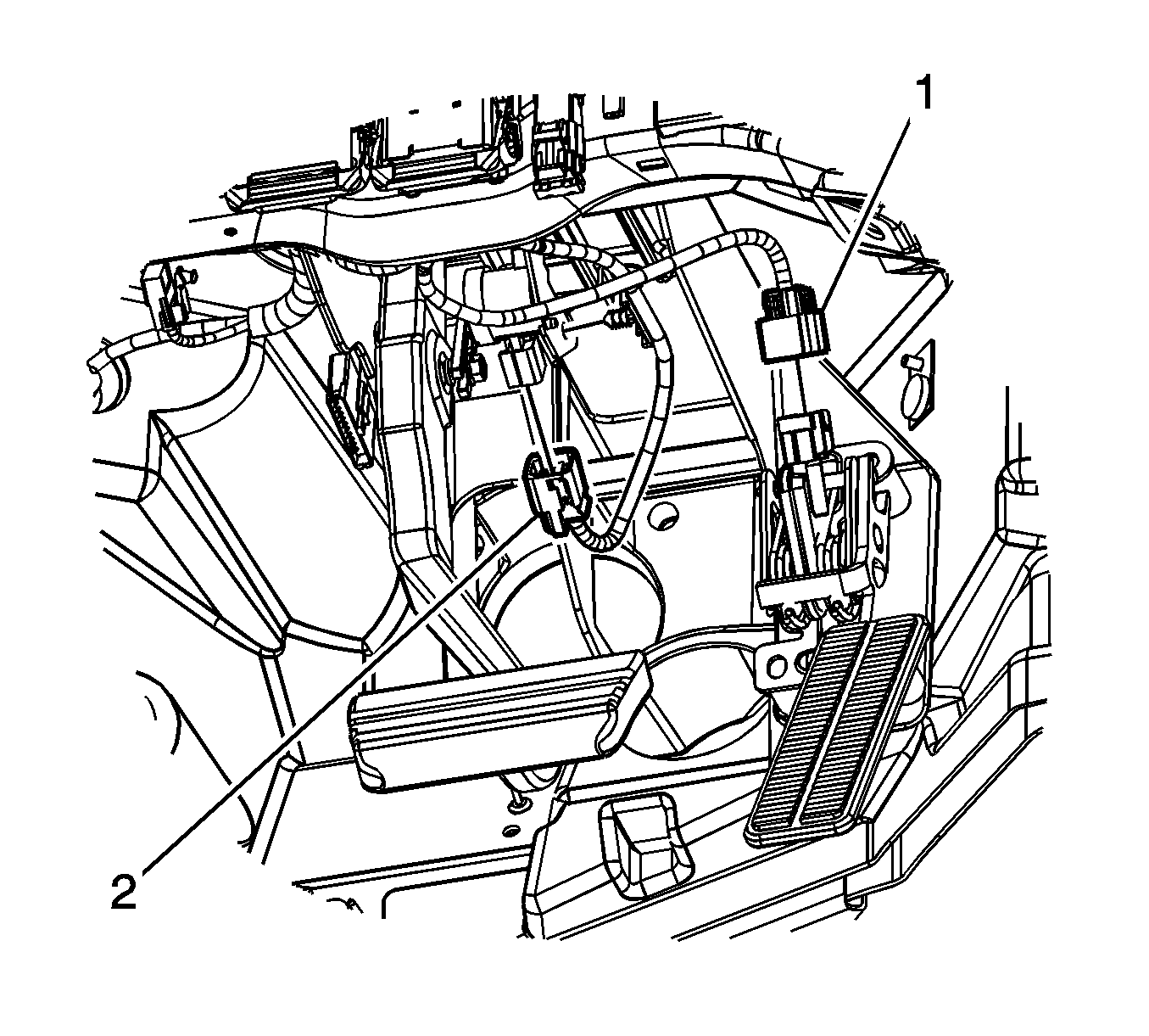
- Disconnect the accelerator pedal position sensor (1) and brake apply sensor (2).
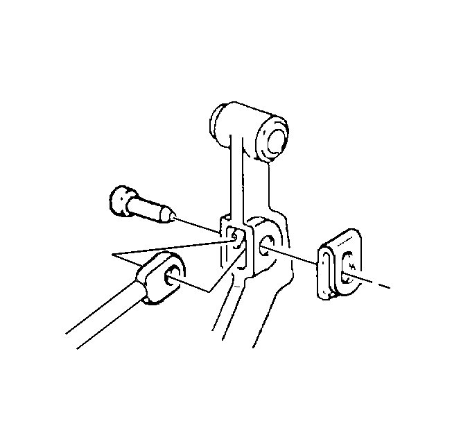
- Remove the retainer, washer, brake booster pushrod, and brake pedal pin from the brake pedal.
- Reposition the isolation mat by cutting a small slit in the mat.
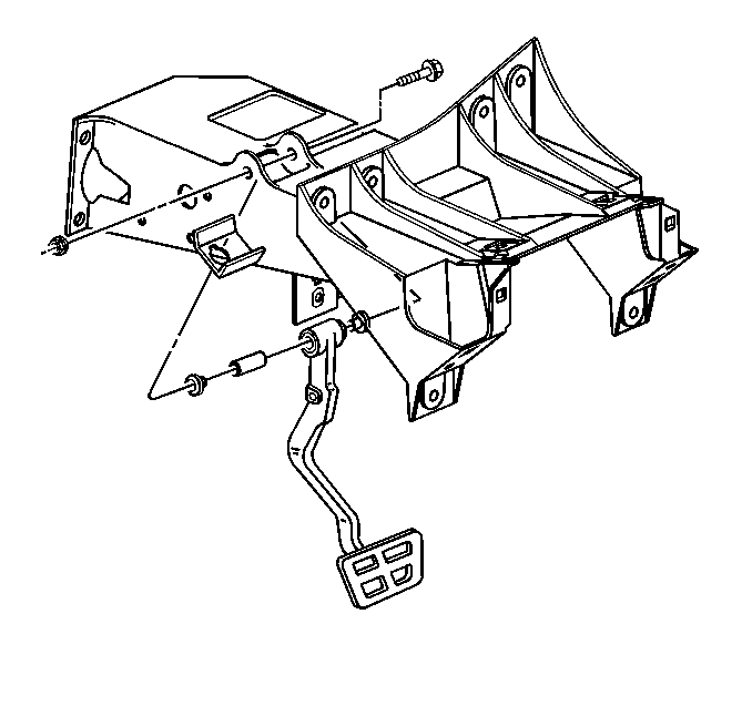
- Remove the brake pedal pivot bolt and nut.
- Remove the brake pedal from the mounting bracket.


Installation Procedure
- Lubricate the bushings, pivot bolt, and all friction parts with high temperature silicone brake lubricant.
- Install the brake pedal to the mounting bracket.
- Install the pivot bolt and nut.
- Reposition the dash isolation mat.
- Install the retainer, washer, brake booster pushrod, and brake pedal pin to the brake pedal. Verify proper engagement of the retainer to the brake pedal pin by rotating the retainer.
- Connect the accelerator pedal position sensor (1) and brake apply sensor (2).
- Install the instrument panel knee bolster trim panel. Refer to Driver Knee Bolster Panel Replacement.

Caution: Refer to Fastener Caution in the Preface section.
Tighten
Tighten the brake pedal pivot nut to 29 N·m (21 lb ft).


