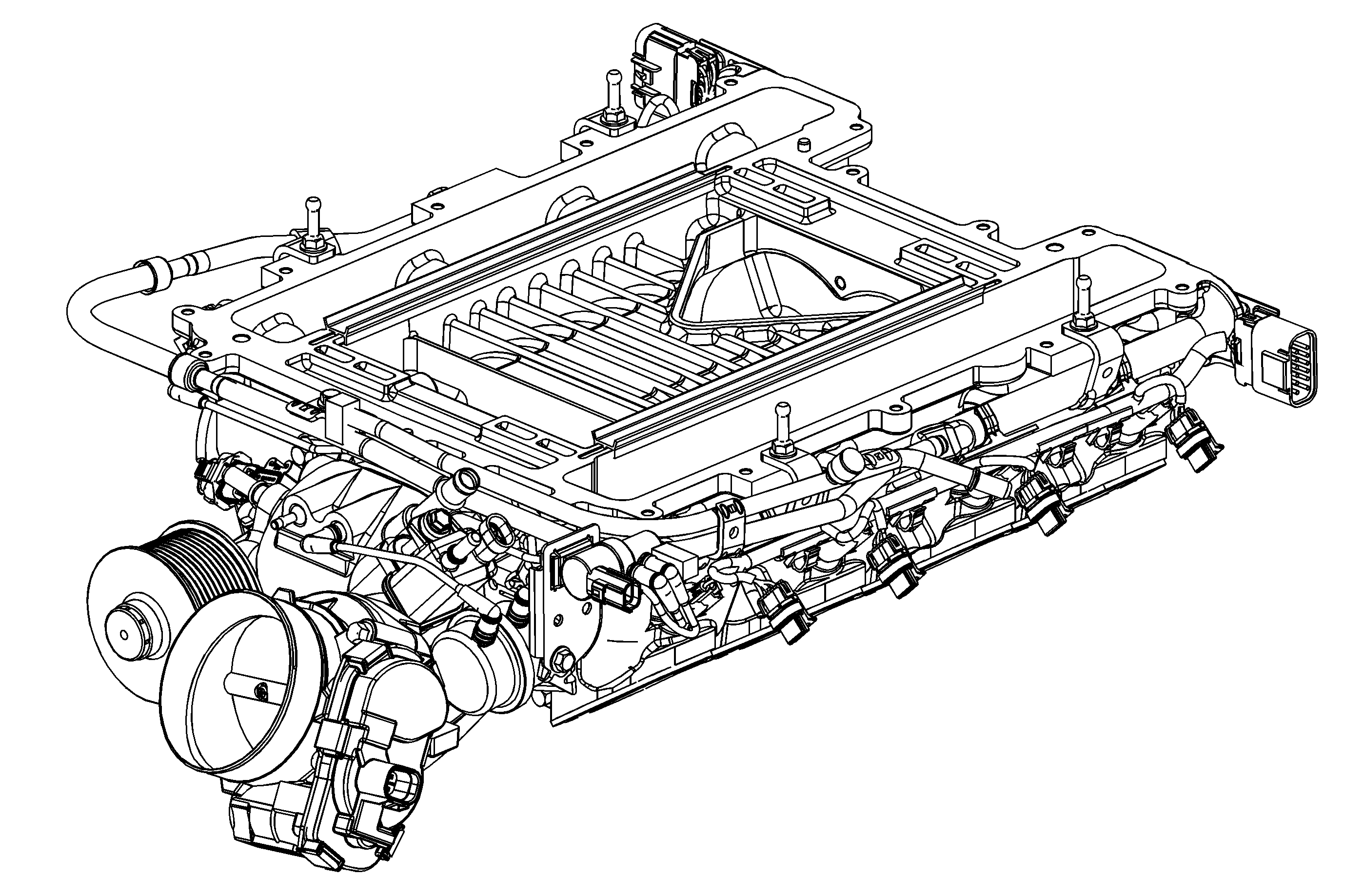
Intake Manifold/Supercharger Assembly
The LS9 Roots type supercharger is a positive displacement pump that consists of 2 counter-rotating rotors installed into the lower intake manifold housing. The rotors are designed with 4 lobes and a helical twist. The rotors of the
supercharger are designed to run at a minimal clearance, not in contact with each other or the housing, and are timed to each other by a pair of precision spur gears which are pressed onto the rotor shafts. The rotors are supported at each end by self-lubricating,
non-serviceable bearings. The drive belt pulley is pressed onto the input shaft and is also not serviceable.
The lower supercharger assembly consists of the following components:
| • | Lower intake manifold housing, to include rotors, gears, bearings, and drive belt pulley |
| • | Charged air bypass valve |
| • | Fuel rail with injectors |
| • | Evaporative emission canister purge valve |
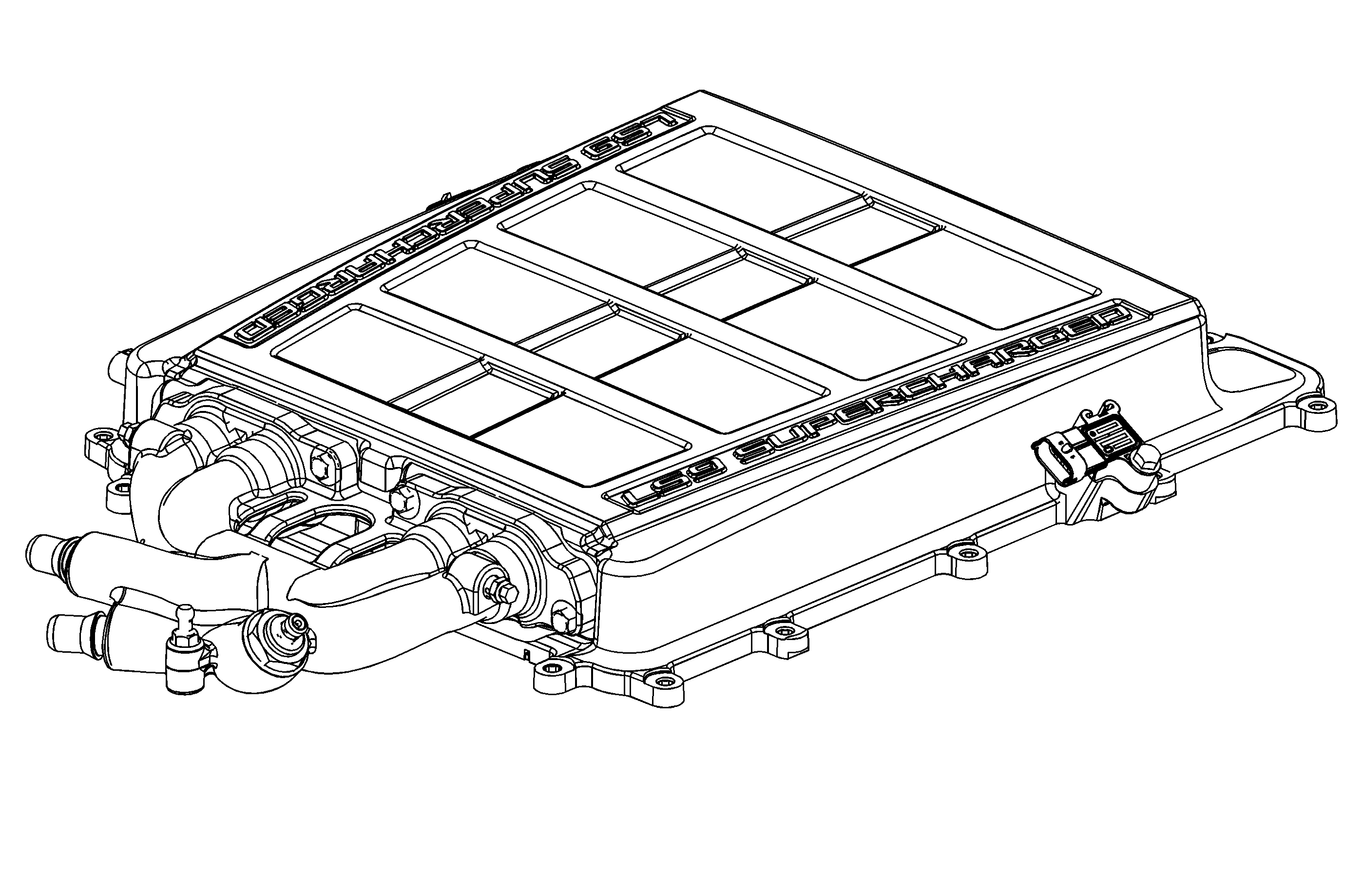
Cover/Intercooler

The cover assembly has an integrated intercooler. Cooling the air enhances the effectiveness of the supercharger. The intercooler uses conventional coolant in a system that is separate from the engine cooling system. The intercooler assembly includes the
cover, two charge air coolers/heat exchangers, a water manifold assembly, two service bleed ports, and a variety of sensors to monitor air temperature and pressure. The water manifold, located at the front of cover transfers coolant to the cover via four internal
transfer tubes. The transfer tubes and water manifold are sealed with o-rings and press-in-place seals. Coolant enters the inlet port of the water manifold assembly, is directed into and through the two charge air coolers/heat exchangers,
and exits back into the water manifold. Coolant then exits the water manifold outlet port returning to the separate cooling system.
The cover/intercooler consists of the following components:
| • | Water manifold assembly |
| • | Charge air cooler cover |
| • | Charge air coolers/heat exchangers |
| • | Intake air temperature (IAT) sensor |
| • | Barometric pressure sensor |
| • | Air outlet pressure sensor |
| • | Service coolant bleed ports |
Operation
The supercharger is designed to increase the air pressure and density in the intake manifold. When this air is mixed with the correct amount of fuel the result is more power from the engine. This excess air creates a boost pressure in the intake manifold
with a maximum engine boost of 72.4 kPa (10.5 psi). Because the supercharger is a positive displacement pump and is directly driven from the engine drive belt system, boost pressure is available at all driving conditions. When boost is not required
in situations such as idle or light throttle cruising, the excess air is routed through an internal bypass passage located between the intake manifold and the supercharger inlet. The bypass circuit is regulated by a bypass valve which is similar to a throttle
plate. Spring force holds the bypass valve in a normally closed position to create boost. The bypass actuator is a vacuum operated valve that is connected to the vacuum signal between the throttle and the supercharger inlet. Vacuum to the actuator pulls the
bypass valve open during idle and light load conditions to decrease boost. The charge air bypass valve is a vacuum/electrically operated solenoid valve that is attached to the supercharger housing. The three-way valve which is controlled by the engine control
module (ECM) which determines when pressure from the manifold is routed to the bypass actuator. The charge air bypass valve allows pressure from the manifold to open the bypass valve and lower boost pressure during specific driving conditions. The open
bypass valve reduces the pumping effort of the supercharger, thereby increasing the fuel efficiency in light load operations.


