Tools Required
J 37088-A Fuel Line Disconnect Tool
Removal Procedure
- Disconnect the negative battery cable. Refer to Battery Negative Cable Disconnection and Connection .
- Drain the fuel tank. Refer to Fuel Tank Draining .
- Raise and support the vehicle. Refer to Lifting and Jacking the Vehicle .
- Remove the left rear tire. Refer to Tire and Wheel Removal and Installation .
- Remove the left rear wheelhouse panel. Refer to Rear Wheelhouse Panel Liner Replacement .
- Remove both mufflers. Refer to Exhaust Muffler Replacement - Left Side and Exhaust Muffler Replacement - Right Side .
- Remove the driveline support assembly. Refer to Driveline Support Assembly Replacement .
- Disconnect the fuel fill hose and recirculation line from the fill pipe.
- Disconnect the fuel pump jumper harness connector.
- Disconnect the fuel feed pipe (4) at the rear of the left fuel tank. Refer to Plastic Collar Quick Connect Fitting Service .
- Cap the fuel pipes to prevent fuel system contamination.
- Loosen the fuel tank strap in order to drop the tank approximately one inch.
- Disengage the crossover tube connector position assurance (CPA) retainer by pulling the tab (1) outward and rotate.
- Rotate crossover tube collar counterclockwise to disengage.
- Disconnect the crossover tube (5) from the left fuel tank by pulling straight out.
- Disconnect the evaporative emission (EVAP) crossover pipe (2) quick connect fitting at the left fuel tank.
- Cap the EVAP pipes (1 and 3) to prevent system contamination.
- Remove the fuel tank strap mount bolts.
- Remove the fuel tank strap from the vehicle.
- Remove the fuel tank.
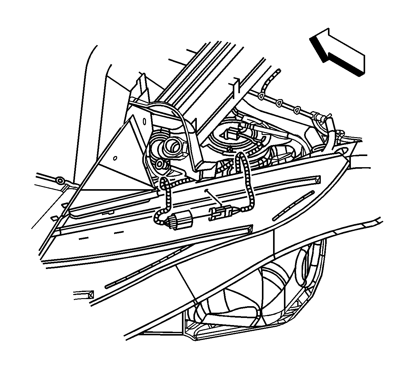
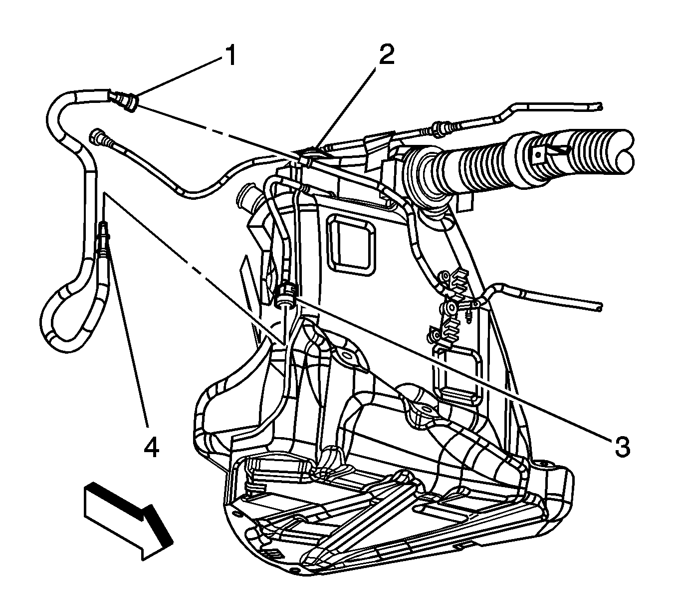
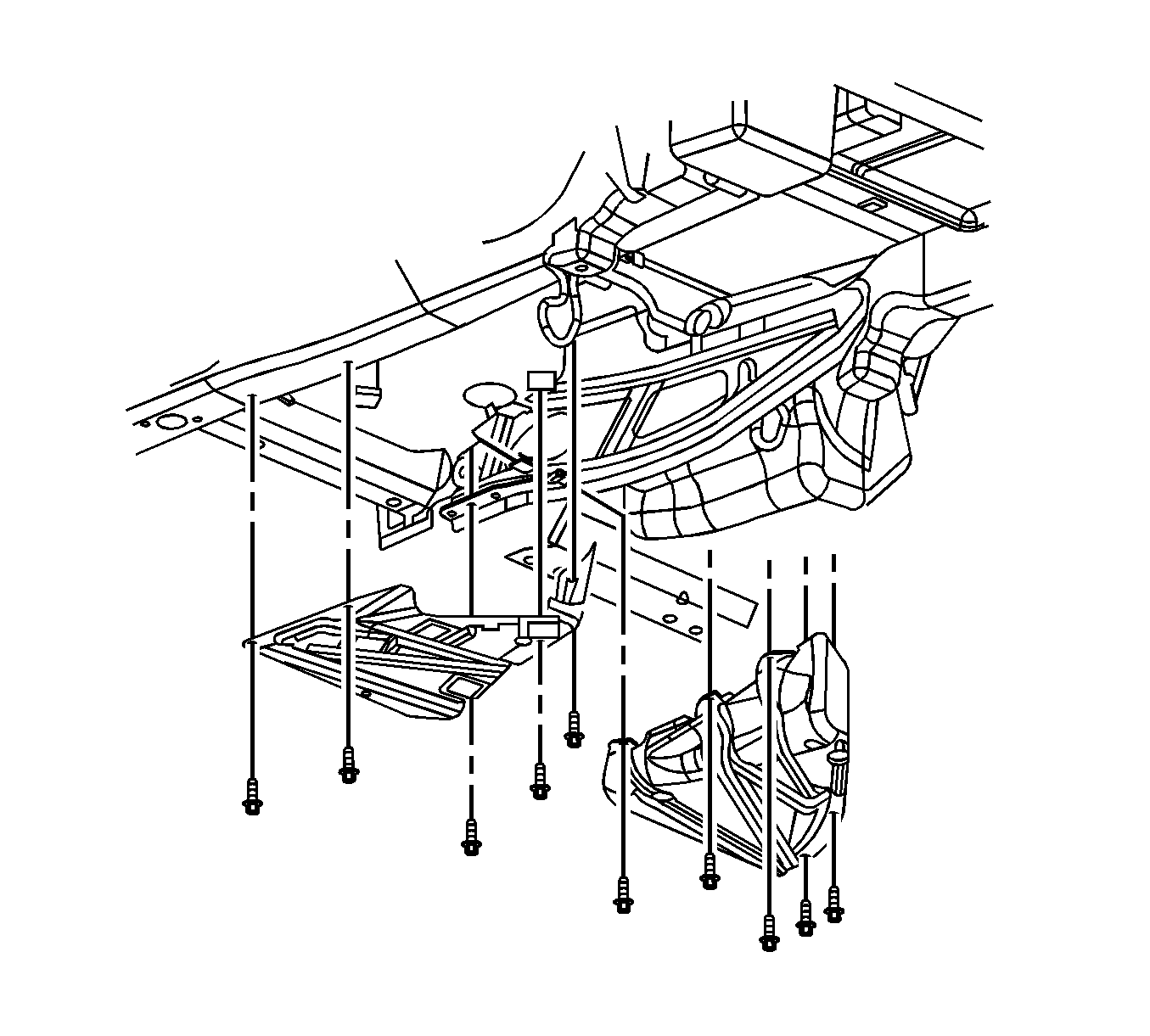
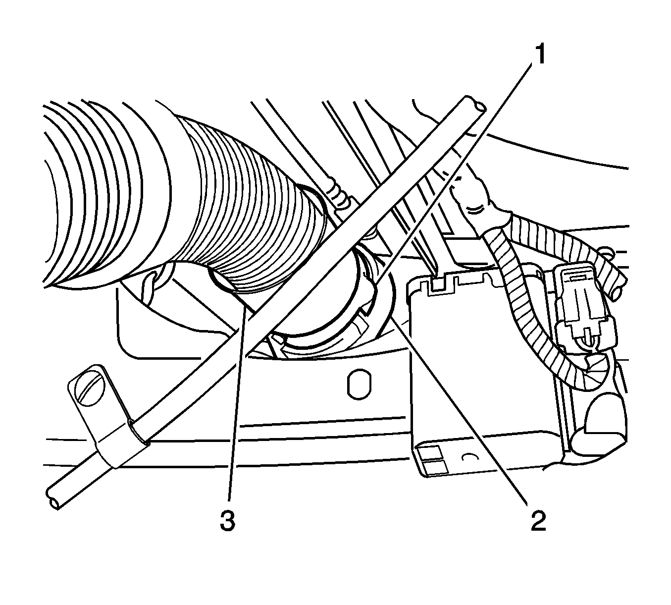
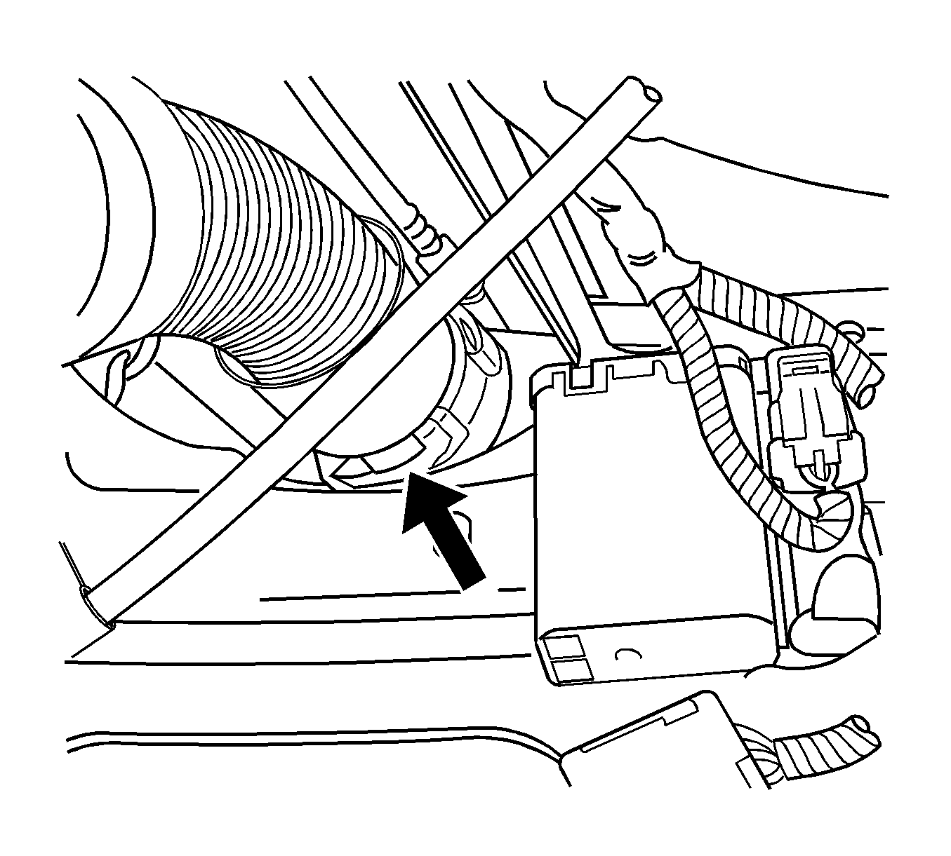
Important: The crossover tube CPA is released when the latch disengages from the tank connection groove.
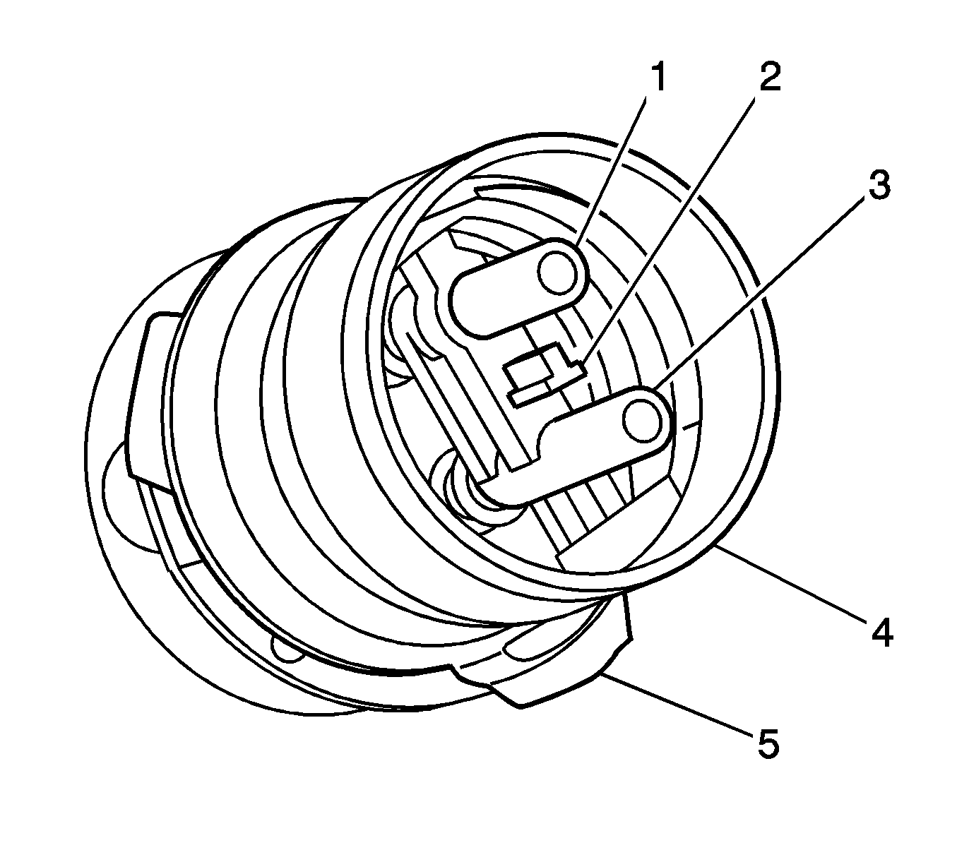
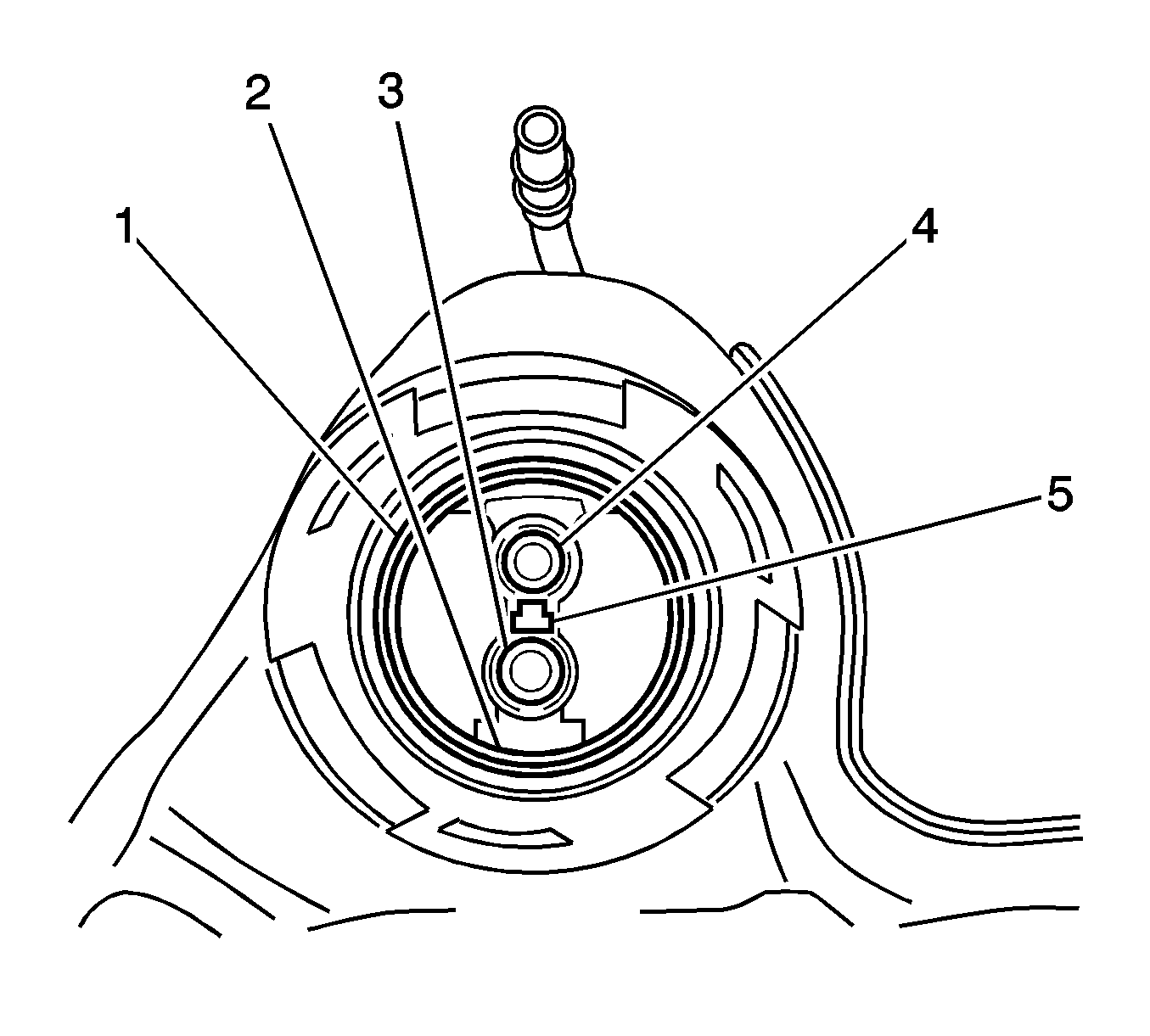
Important: Take care not to disturb the internal O-rings in the fuel tank connections.
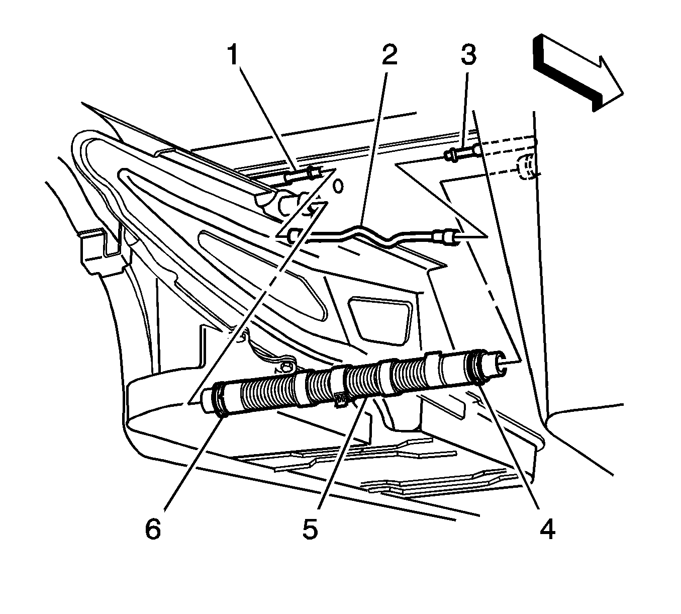

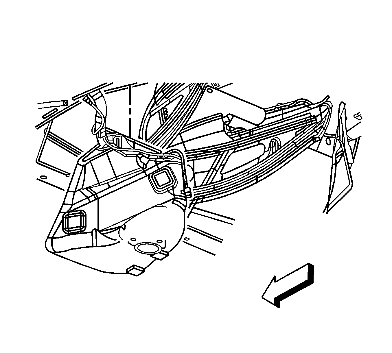
Installation Procedure
- Install the fuel tank.
- Install the fuel tank strap to the vehicle.
- Install the fuel tank strap bolts loosely leaving the tank hanging approximately one inch.
- Remove the caps from the EVAP pipes (1 and 3).
- Connect the EVAP crossover pipe (2) quick connect fitting at the left fuel tank.
- Lubricate the crossover tube to fuel tank connection O-rings (1-4) with GM P/N 1051717 (Canadian P/N 5728223) rubber lubricant.
- Lubricate the crossover tube O-ring mating surfaces (1-4) with GM P/N 1051717 (Canadian P/N 5728223) rubber lubricant.
- Connect the crossover tube to the left fuel tank using the features previously noted.
- Rotate the crossover tube collar (3) clockwise to engage the tangs.
- Rotate the crossover tube CPA retainer counterclockwise past the collar latching tang and push the tab (1) into the locked position.
- Test the crossover tube to fuel tank connection by attempting to rotate the crossover tube collar counterclockwise.
- Tighten the fuel tank strap bolts.
- Remove the cap from the fuel pipes.
- Connect the fuel feed pipe (4) at the rear of the left fuel tank. Refer to Plastic Collar Quick Connect Fitting Service .
- Connect the fuel pump jumper harness connector.
- Connect the fuel fill hose and recirculation line to the fill tube.
- Install the driveline support assembly. Refer to Driveline Support Assembly Replacement .
- Install both mufflers. Refer to Exhaust Muffler Replacement - Left Side and Exhaust Muffler Replacement - Right Side .
- Install the left rear wheelhouse panel. Refer to Rear Wheelhouse Panel Liner Replacement .
- Install the Left rear tire. Refer to Tire and Wheel Removal and Installation .
- Lower the vehicle.
- Refuel the fuel tank.
- Connect the negative battery cable. Refer to Battery Negative Cable Disconnection and Connection .
- Perform the following procedure in order to test for leaks:
- Program the transmitters. Refer to Transmitter Programming .


Important: Note the location of the T-shaped alignment feature (5) between the jet pump feed/return pipes connector.

Important: Note the T-shaped alignment feature on the crossover tube.
Important: The crossover tube will not fully seat into the fuel tank if the jet pump lines are misaligned.
Important: The crossover tube collar tangs will not latch if misalignment exists.

Important: If the CPA retainer is locked into position, the crossover tube collar will not rotate.
Notice: Refer to Fastener Notice in the Preface section.

Tighten
Tighten the bolts to 25 N·m (18 lb in).


Tighten
Tighten the clamp to 4 N·m (35 lb in).
| 24.1. | Turn ON the ignition switch for 2 seconds. |
| 24.2. | Turn OFF the ignition for 10 seconds. |
| 24.3. | Turn ON the ignition. |
| 24.4. | Inspect for fuel leaks. |
