Body Lock Pillar Outer Panel Replacement Corvette
Removal Procedure
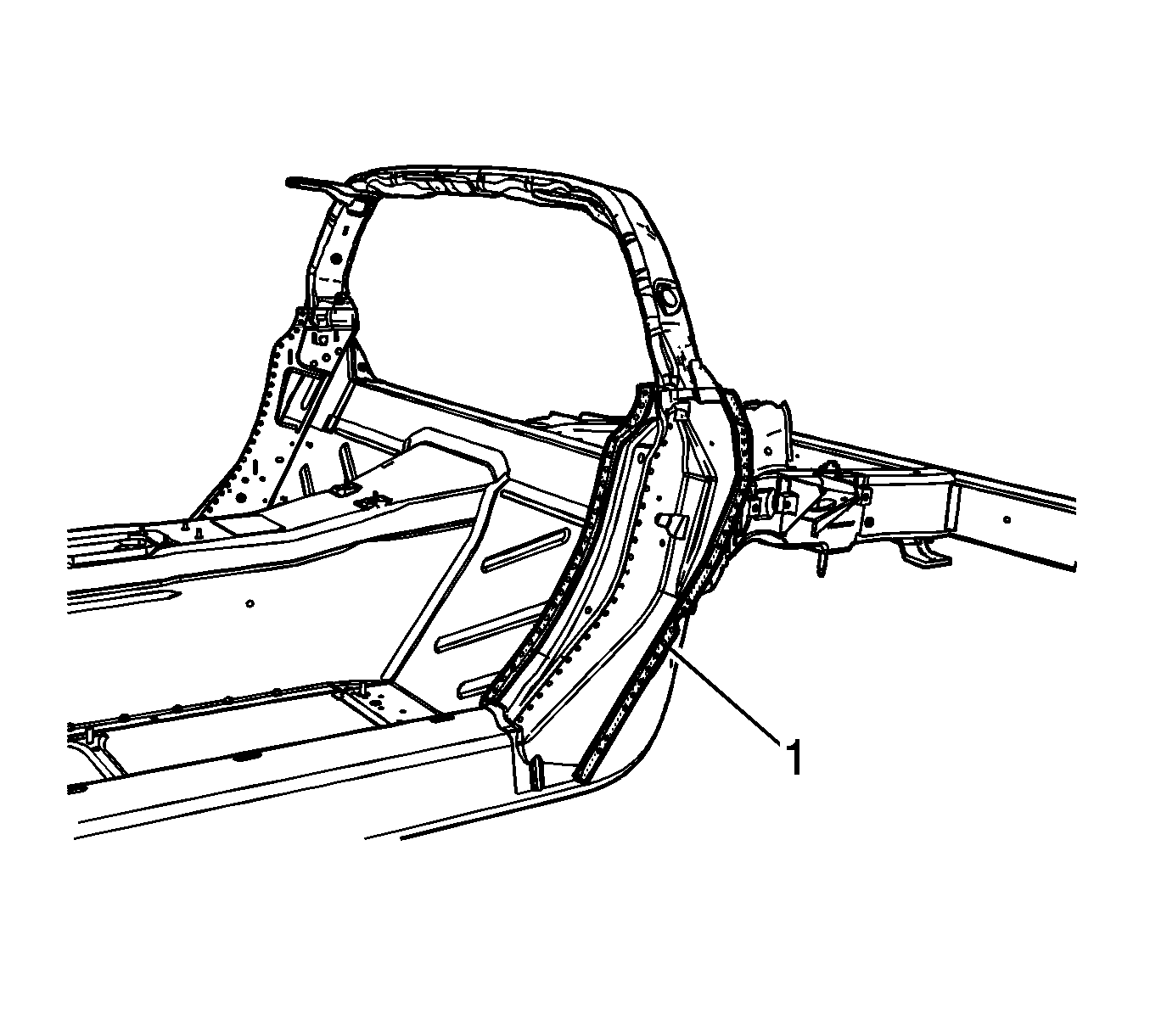
Service the replacement outer lock pillar panel as an assembly. Remove and replace the side door opening panel in order to replace the outer lock pillar panel.
- Disable the SIR system. Refer to SIR Disabling and Enabling .
- Disconnect the negative battery cable. Refer to Battery Negative Cable Disconnection and Connection .
- Remove all related panels and components.
- Repair as much of the damage as possible to factory specifications. Refer to Dimensions - Body .
- Note the location of the sealers and anti-corrosion materials and remove these components from the repair area as necessary. Refer to Anti-Corrosion Treatment and Repair .
- Locate and drill out all factory welds. Note the number and the location of the welds for installation of the replacement part.
- Remove the damaged outer lock pillar.
Caution: Refer to Approved Equipment for Collision Repair Caution in the Preface section.
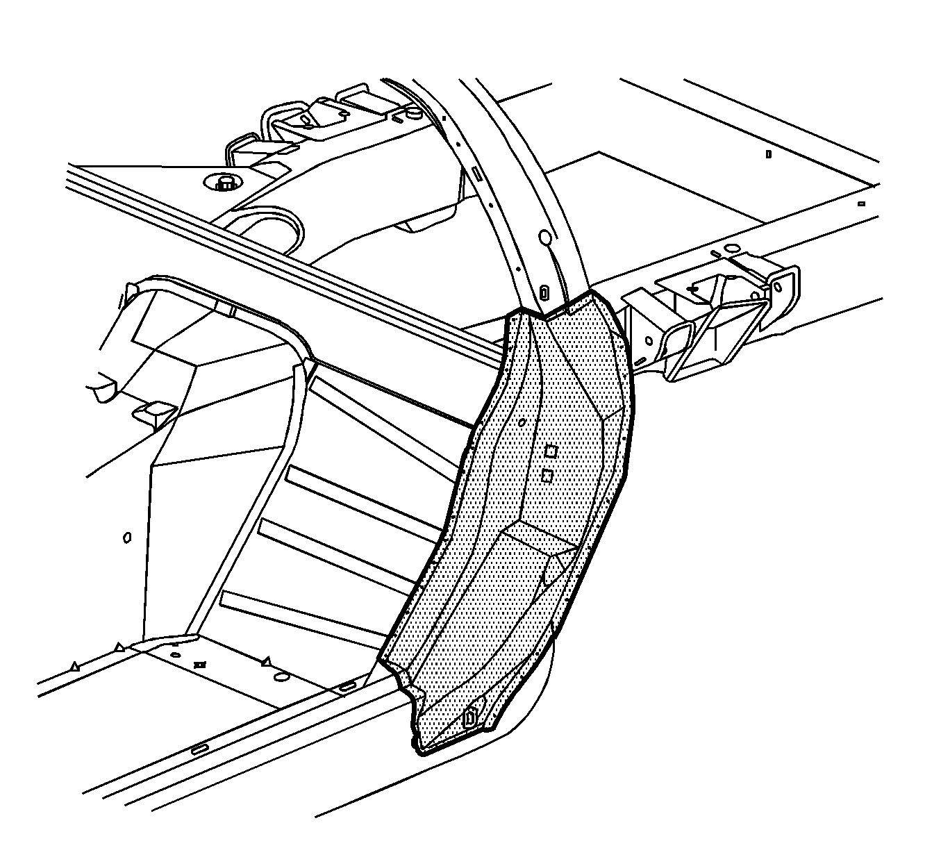
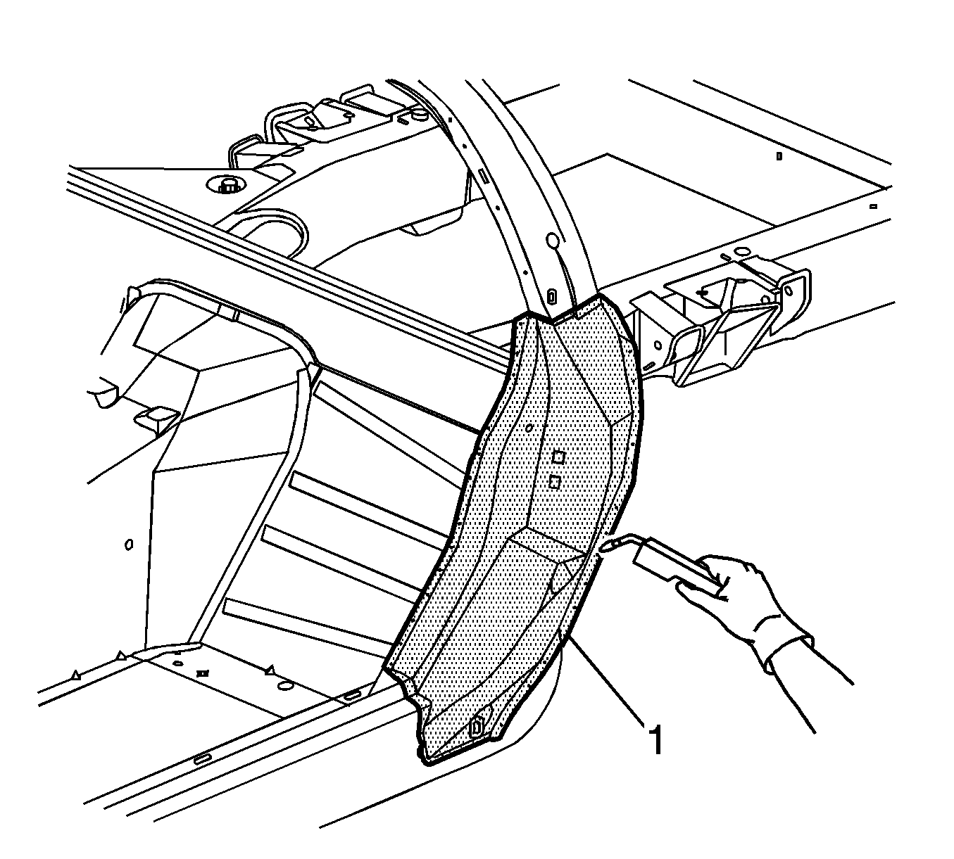
Caution: Refer to Sound Deadener Foam in the Lock Striker Pillars Caution in the Preface section.
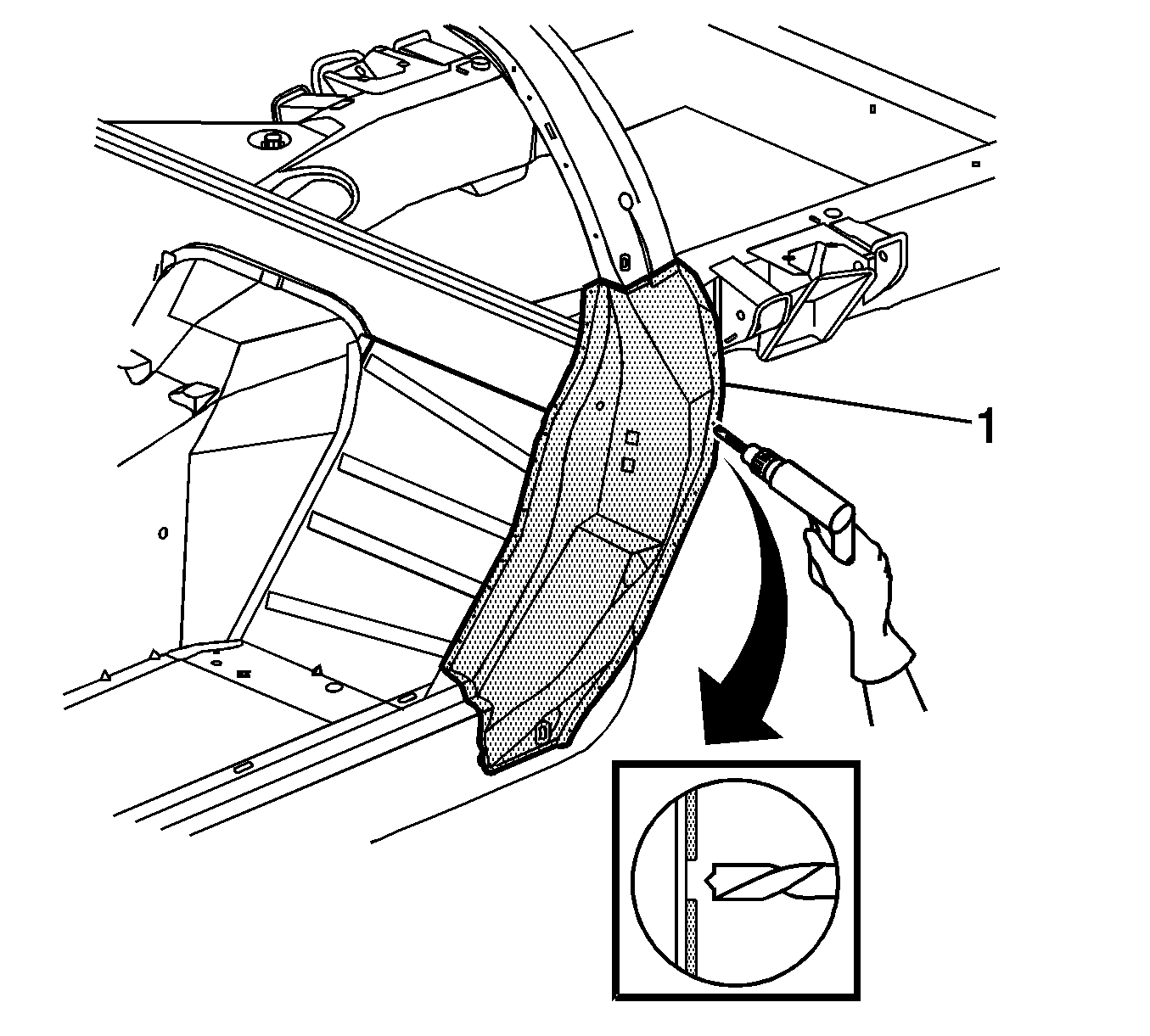
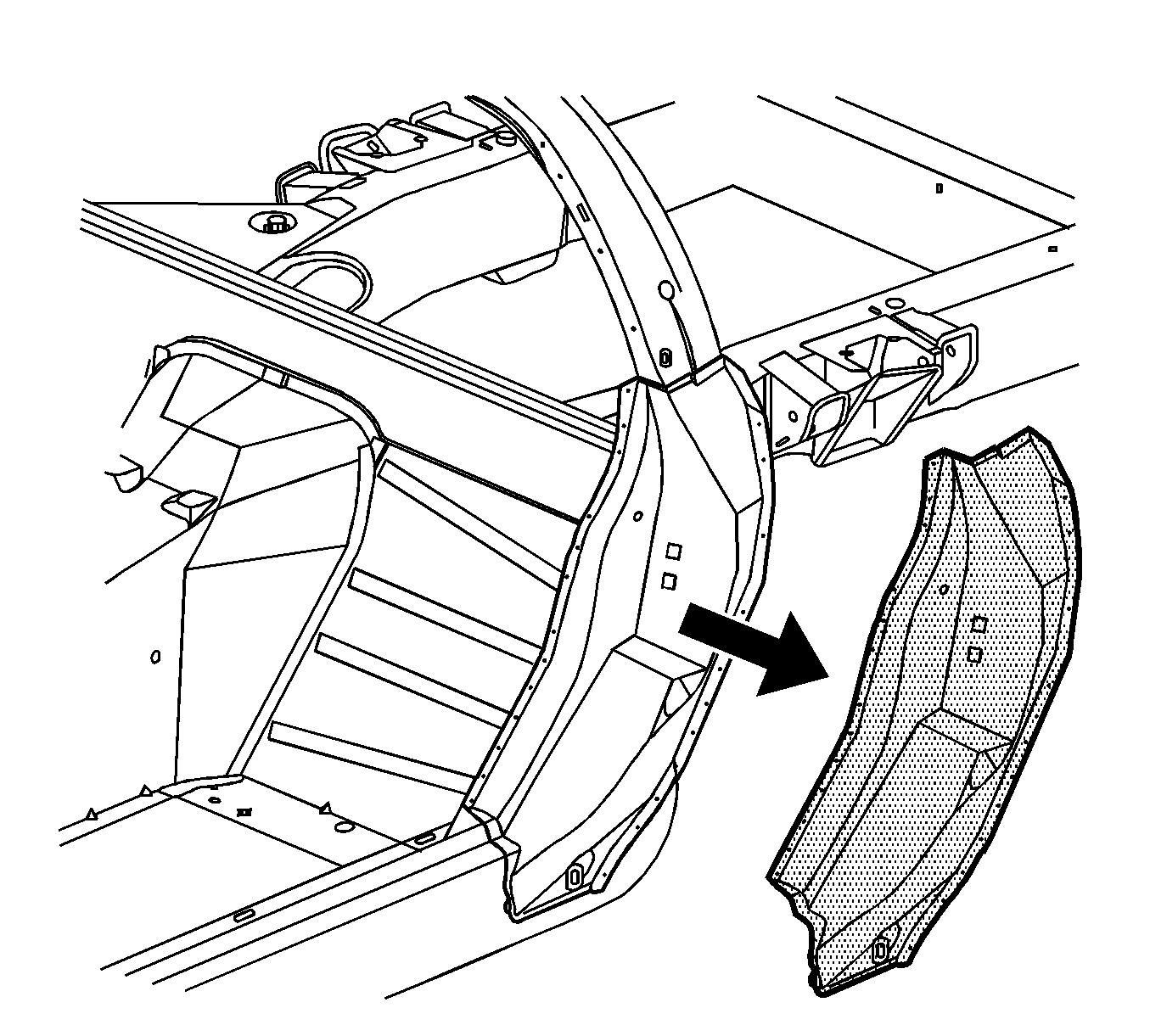
Installation Procedure
- Drill 8 mm (5/16 in) plug weld holes in the service part as necessary in the locations noted on the original panel.
- Prepare all attachment surfaces as necessary.
- Apply GM-approved Weld-Thru Coating or equivalent to all mating surfaces. Refr to Anti-Corrosion Treatment and Repair .
- Position the outer lock pillar.
- Plug weld accordingly.
- Apply the sealers and the anti-corrosion materials to the repair area, as necessary. Refer to Anti-Corrosion Treatment and Repair .
- Paint the repair area. Refer to Basecoat/Clearcoat Paint Systems .
- Install all related panels and components.
- Connect the negative battery cable. Refer to Battery Negative Cable Disconnection and Connection .
- Enable the SIR system. Refer to SIR Disabling and Enabling .
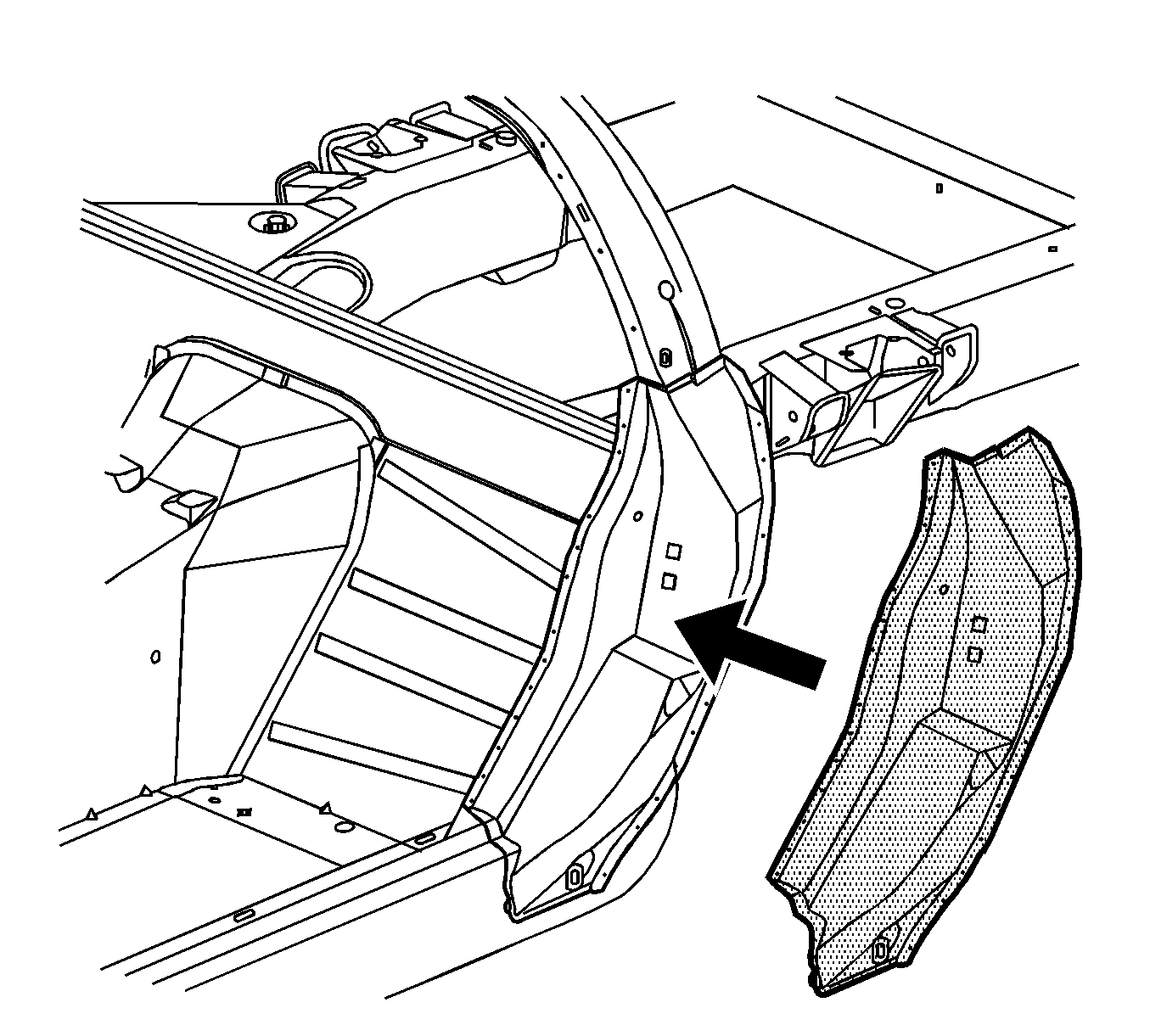
Caution: Refer to Sound Deadener Foam in the Lock Striker Pillars Caution in the Preface section.
Body Lock Pillar Outer Panel Replacement Z06
Removal Procedure
The replacement outer lock pillar panel can be serviced as an assembly or as the outer panel only. Remove and replace the side door opening panel in order to replace the outer lock pillar panel.
- Disable the SIR system. Refer to SIR Disabling and Enabling.
- Disconnect the negative battery cable. Refer to Battery Negative Cable Disconnection and Connection.
- Remove all related panels and components.
- Repair as much of the damage as possible to factory specifications. Refer to Dimensions - Body.
- Note the location of the sealers and anti-corrosion materials and remove these components from the repair area as necessary. Refer to Anti-Corrosion Treatment and Repair.
- Locate and remove all factory welds. Note the number and the location of the welds for installation of the replacement part.
- Using a drill with a 6 mm (1/4 in) bit, locate and remove all SPR’s. Note the number and location of the SPRs for installation of the replacement part.
- Remove the damaged outer lock pillar.
Caution: Refer to Approved Equipment for Collision Repair Caution in the Preface section.
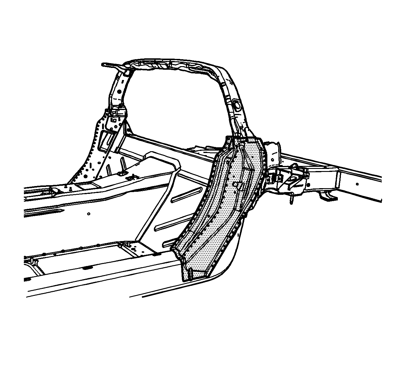
Caution: Refer to Sound Deadener Foam in the Lock Striker Pillars Caution in the Preface section.
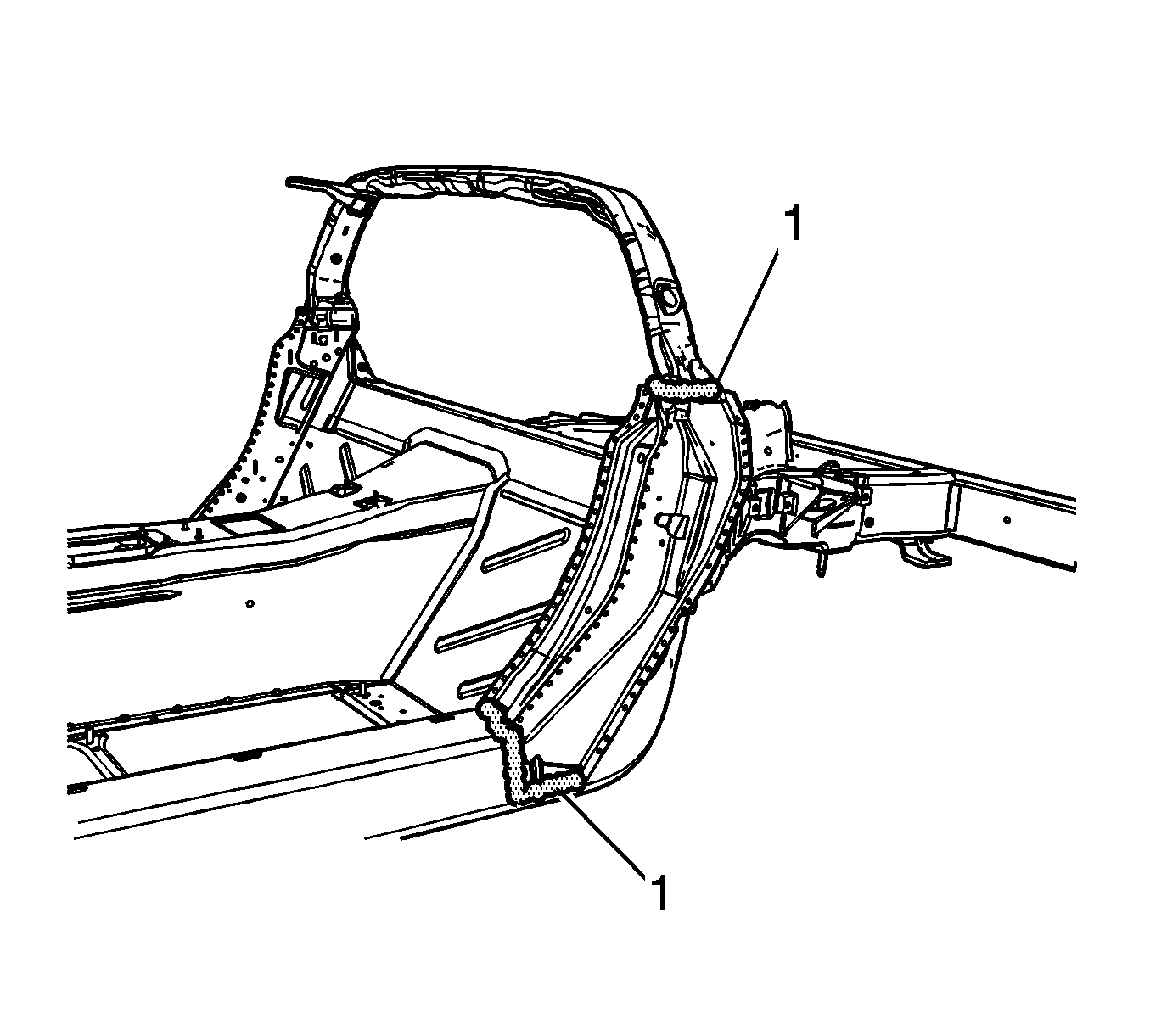
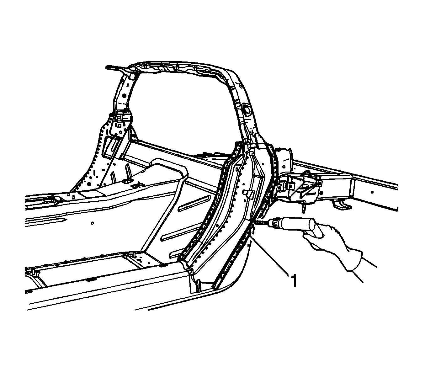
Important: PULSED-MIG (P-MIG) welding is an OPTION for replacing self-piercing rivets (SPR). Drill 10 mm (3/8 in) plug weld holes for each SPR.
Installation Procedure
- Position the outer lock pillar.
- Drill 6 mm (1/4 in) holes in the service part as necessary in the locations noted on the original panel.
- Use an oversize drill bit to countersink the drilled-out hole.
- Using a rivet gun, attach the lock pillar with structural monobolt rivets to the structure duplicating the number of factory SPRs.
- Using a PULSED-MIG (P-MIG) welder, weld the lock pillar to the structure duplicating the factory welds.
- Apply the sealers and the anti-corrosion materials to the repair area, as necessary. Refer to Anti-Corrosion Treatment and Repair.
- Paint the repair area. Refer to Basecoat/Clearcoat Paint Systems.
- Install all related panels and components.
- Connect the negative battery cable. Refer to Battery Negative Cable Disconnection and Connection.
- Enable the SIR system. Refer to SIR Disabling and Enabling.

Important: Replace the SPRs with a structural monobolt rivet, GM P/N 19120691.
The structural monobolt rivet requires a special nose tip SPX P/N BO48073.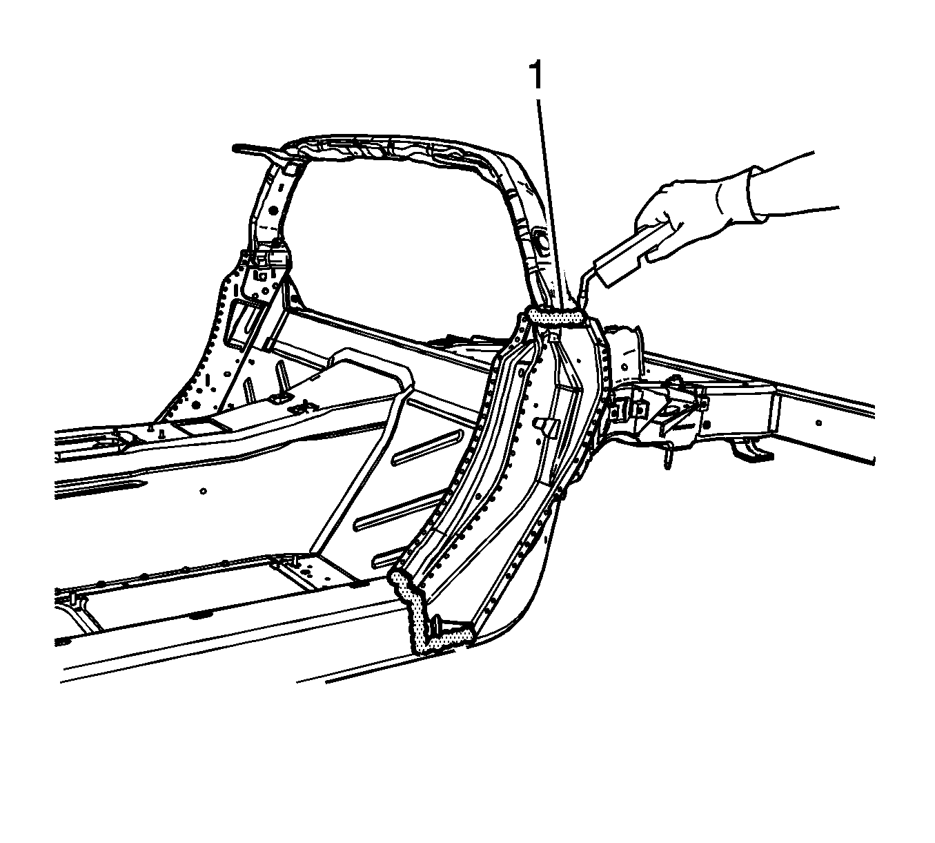
Important: Recommended wire alloy is 5356 and wire size is.035. The shielding gas is 100 percent Argon.
A 2 minute cooling down period is recommended for every 2 minutes or 100 mm (4 in) of welding.