SMU - Addition of Aluminum Frame Thread Repair Procedure

| Subject: | Addition of Aluminum Frame Thread Repair Procedure |
| Models: | 2006 Chevrolet Corvette Z06 |
This bulletin is being issued to add the Aluminum Frame Thread Repair procedure in the Frame and Underbody sub-section of the Service Manual.
The following information has been updated within SI. If you are using a paper version of this Service Manual, please make a reference to this bulletin on the affected page.
Aluminum Frame Thread Repair
Tools Required
CH 48106 Suspension Thread Repair Kit
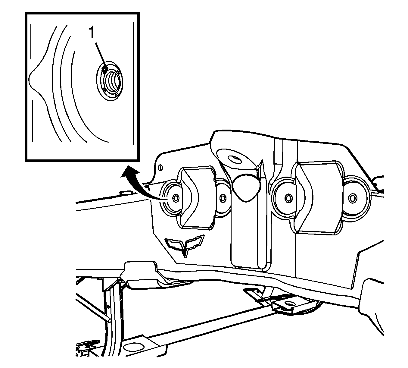
The suspension thread repair Procedure involves a solid, thin-walled, key-locking, stainless steel keysert. Use the keysert when the parent material of the original threaded insert is damaged.
Caution: Refer to Safety Glasses Caution.
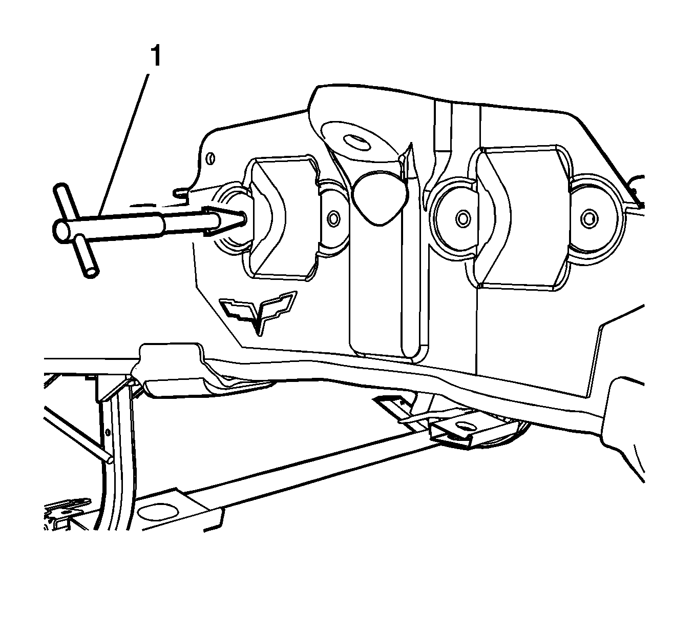
- Install the CH-48106-1 extracting tool (1) into the damaged wire insert.
- Set the extracting tool by lightly tapping the tool with a mallet.
- Remove the wire insert by turning the tool counter-clockwise, while applying light forward pressure on the tool.
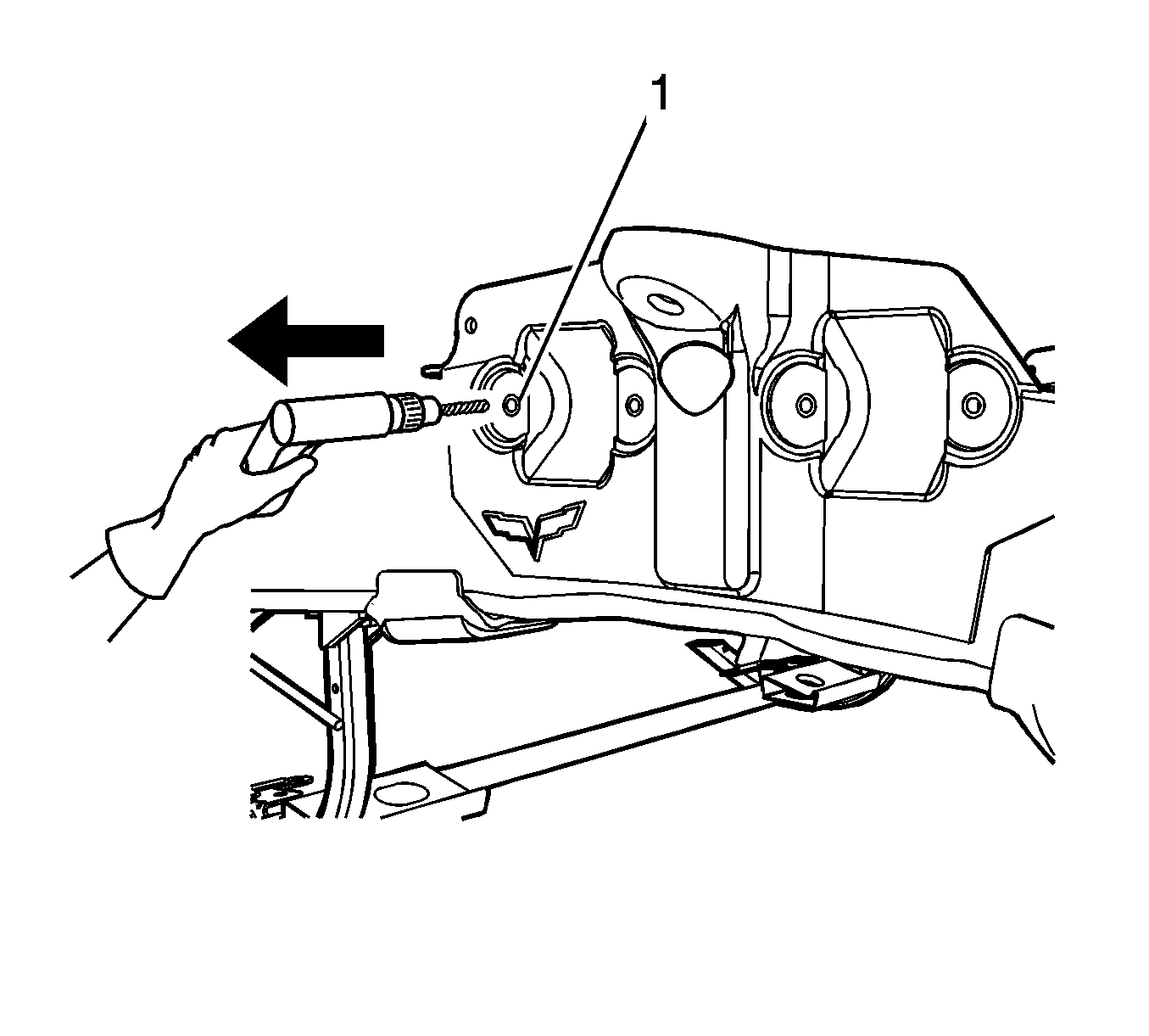
- Use the CH-48106-2 12.8 mm drill bit to drill out the threads (1) of the damaged hole. Drill to a minimum depth of 14.5 mm (3/8 in)
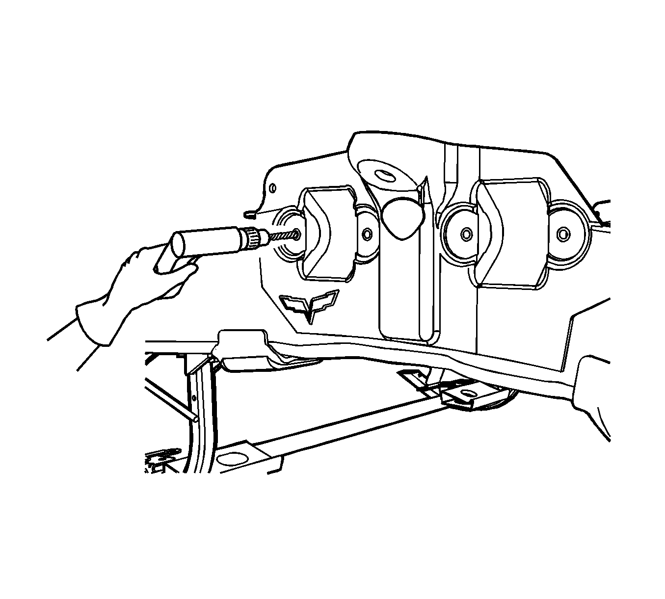
- Use compressed air (1) to clean out any chips.
- Use a CH 48106-3 chamfering tool or an oversize drill bit of 14.25 mm (3/8 in) to countersink the drilled-out hole.
- Use compressed air (1) to clean out any chips.
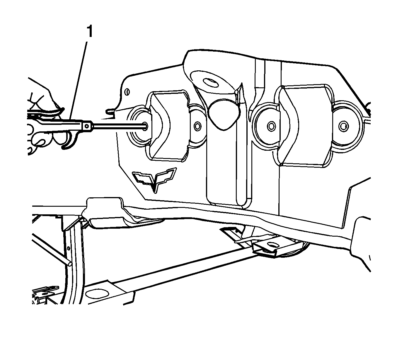
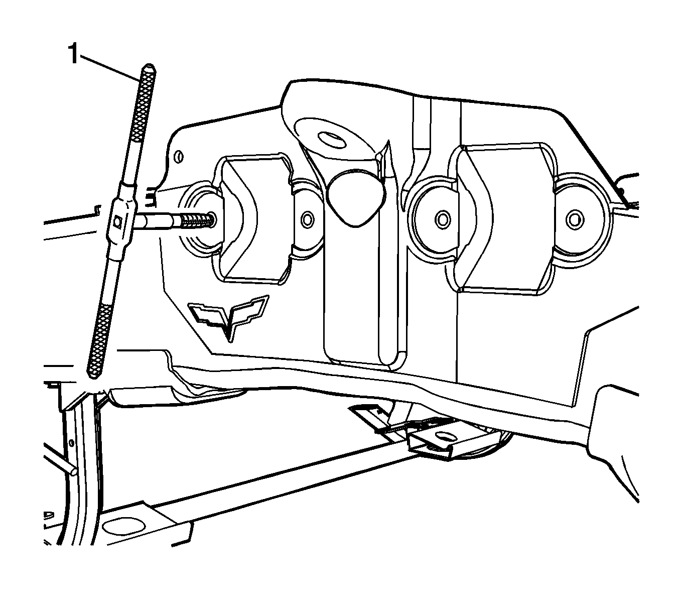
- Use CH-48106-8 cutting oil to lubricate the threads of the tap.
- Install the CH-48106-6 tap socket or equivalent tool to the CH-48106-4 tap.
- Use the CH-48106-4 M14-1.5 6H Tap (1) to tap new threads in the drilled hole. Tap the threads to a minimum depth of 13.5 mm (5/16 in).
- Use compressed air (1) to clean out any chips.
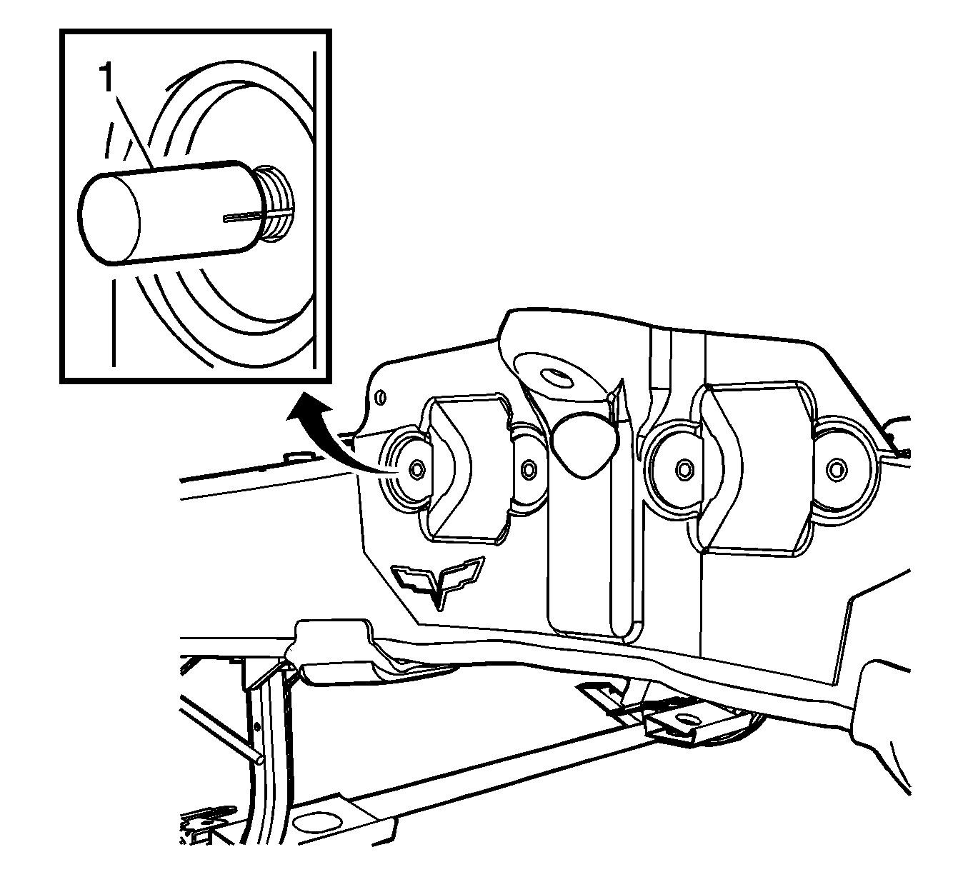
- Install the CH-48106-7 keysert into the slotted sections of the CH-48106-5 installation tool (1).
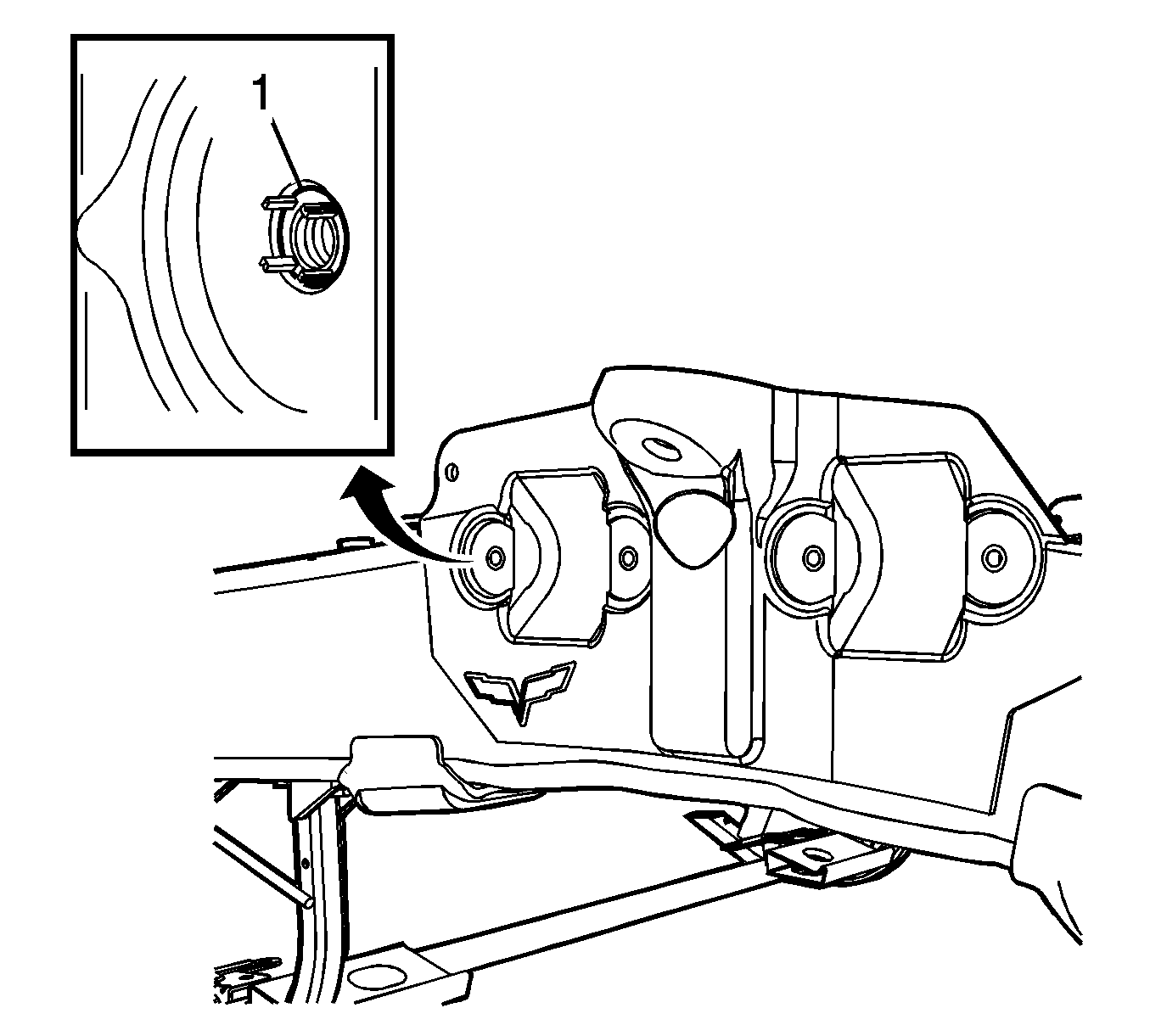
- Use the CH-48106-5 installation tool to install the keysert in the tap hole slightly below the bottom of the countersunk surface (1).
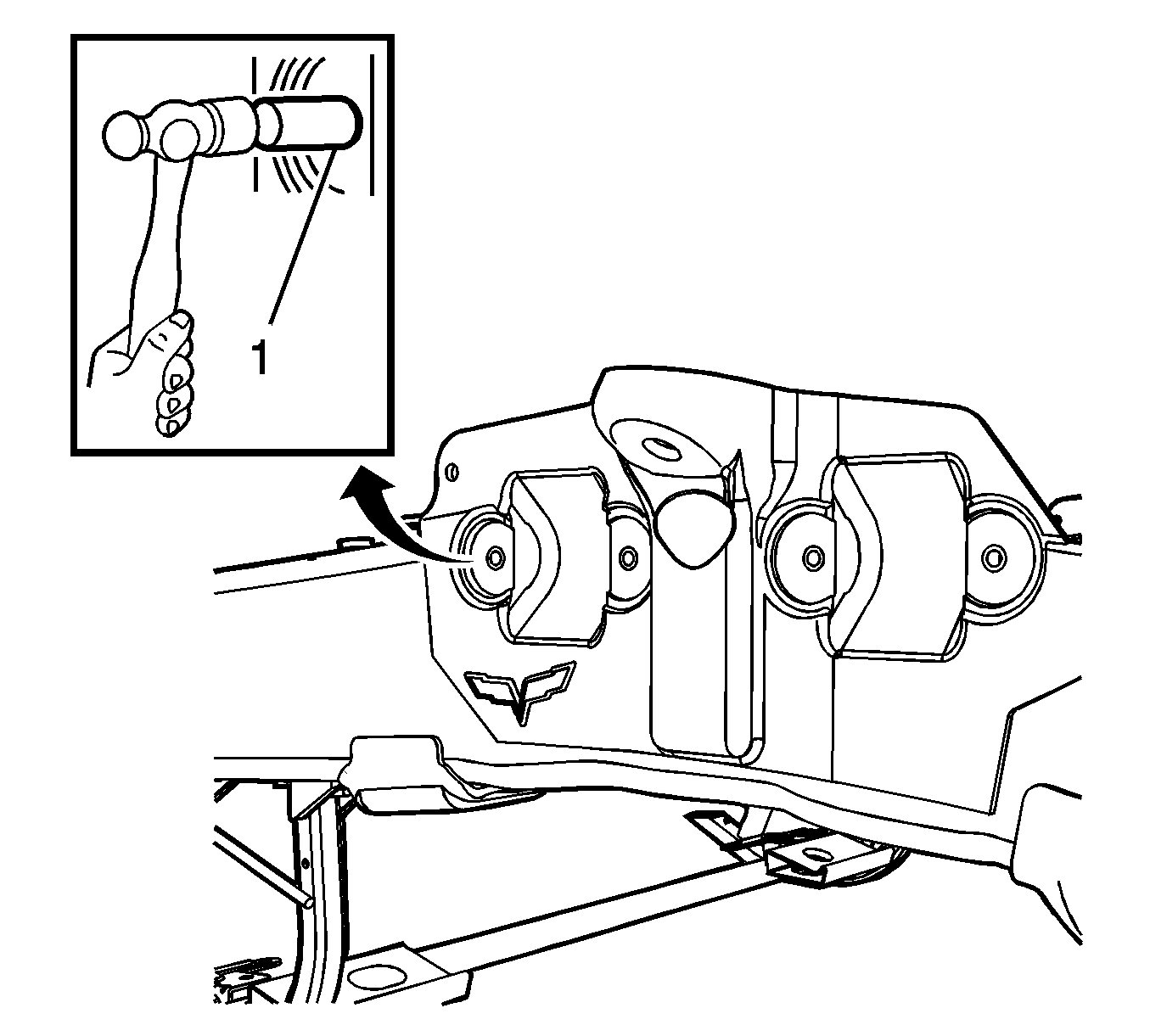
- Remove the CH-48106-5 installation tool from the keys. Rotate the tool so that the keys are aligned on the flat surface of the tool.
- Use a mallet to strike the top of the CH-48106-5 installation tool (1) as necessary to drive the keys into the threaded parent material until the keys are even or slightly below the surface.
- Inspect the keysert (1) for proper installation into the hole.
- Install the suspension bolt. Tighten the bolt.
- Verify that the suspension bolt is seated flush to the surface.
Important: The keysert will install more easily if you countersink the hole.


Important: The keys mechanically lock the keysert to the threaded parent material.
Important: If necessary, add shims or washers to the suspension bolt to check the torque and flushness of the bolt.
Tighten
Tighten the suspension bolt to 91 N·m(67 lb ft).
