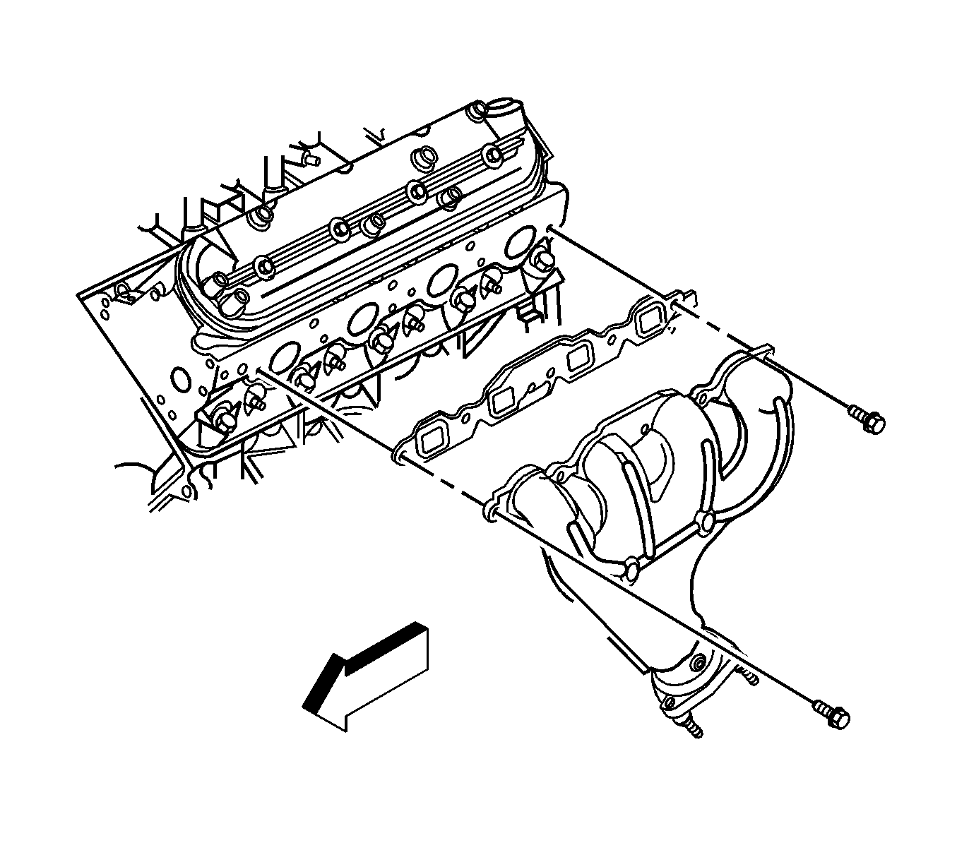
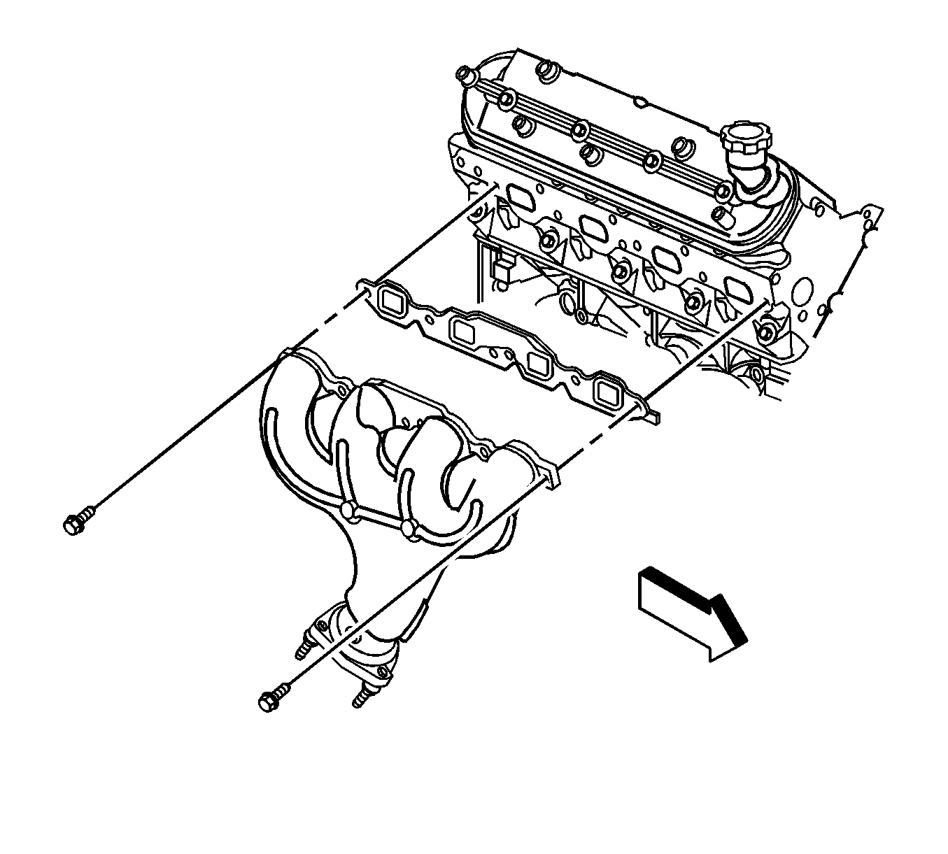
Exhaust Manifold Replacement - Left Side 6.0L
Removal Procedure
- Remove the engine sight cover. Refer to Upper Intake Manifold Sight Shield Replacement .
- Remove the bank 1, sensor 1 oxygen sensor from the exhaust manifold. Refer to Heated Oxygen Sensor Replacement - Bank 1 Sensor 1 .
- Remove the spark plugs. Refer to Spark Plug Replacement .
- Remove the generator. Refer to Generator Replacement .
- Remove the catalytic convertor. Refer to Catalytic Converter Replacement - Left Side .
- Remove the exhaust manifold bolts.
- Remove the exhaust manifold.
Notice: Refer to Excessive Force and Oxygen Sensor Notice in the Preface section.

Important: It may be necessary to remove the heat assembly from the exhaust manifold to gain enough clearance to remove the exhaust manifold.
Installation Procedure
Important: Tighten the exhaust manifold bolts as specified in the service procedure. Improperly installed and/or leaking exhaust manifold gaskets may effect vehicle emissions and/or On-Board Diagnostics (OBD) II system performance.
The cylinder head exhaust manifold bolt hole threads must be cleaned and free of debris or threadlocking material.- Install the catalytic convertor.
- Apply a 5 mm (0.2 in) wide band of threadlock GM P/N 12345493 (Canadian P/N 10953489), or equivalent to the threads of the exhaust manifold bolts.
- Position the exhaust manifold and a NEW gasket into place.
- Install the exhaust manifold bolts.
- Tighten the exhaust manifold bolts a first pass to 15 N·m (11 lb ft). Tighten the exhaust manifold bolts beginning with the center 2 bolts. Alternate from side-to-side, working toward the outside bolts.
- Tighten the exhaust manifold bolts a final pass to 25 N·m (18 lb ft). Tighten the exhaust manifold bolts beginning with the center 2 bolts. Alternate from side-to-side, working toward the outside bolts.
- Install the bank 1, sensor 1 oxygen sensor in the exhaust manifold oxygen sensor. Refer to Heated Oxygen Sensor Replacement - Bank 1 Sensor 1 .
- Install the spark plugs. Refer to Spark Plug Replacement .
- Install the generator. Refer to Generator Replacement .
- Install the engine sight cover. Refer to Upper Intake Manifold Sight Shield Replacement .
- Install the catalytic convertor. Refer to Catalytic Converter Replacement - Left Side .
Important: In the following service procedure, position the catalytic convertor on the intermediate pipe, but DO NOT tighten the clamp. Leave it loose to allow the alignment of the exhaust manifold on the cylinder head.

Notice: Refer to Fastener Notice in the Preface section.
Tighten
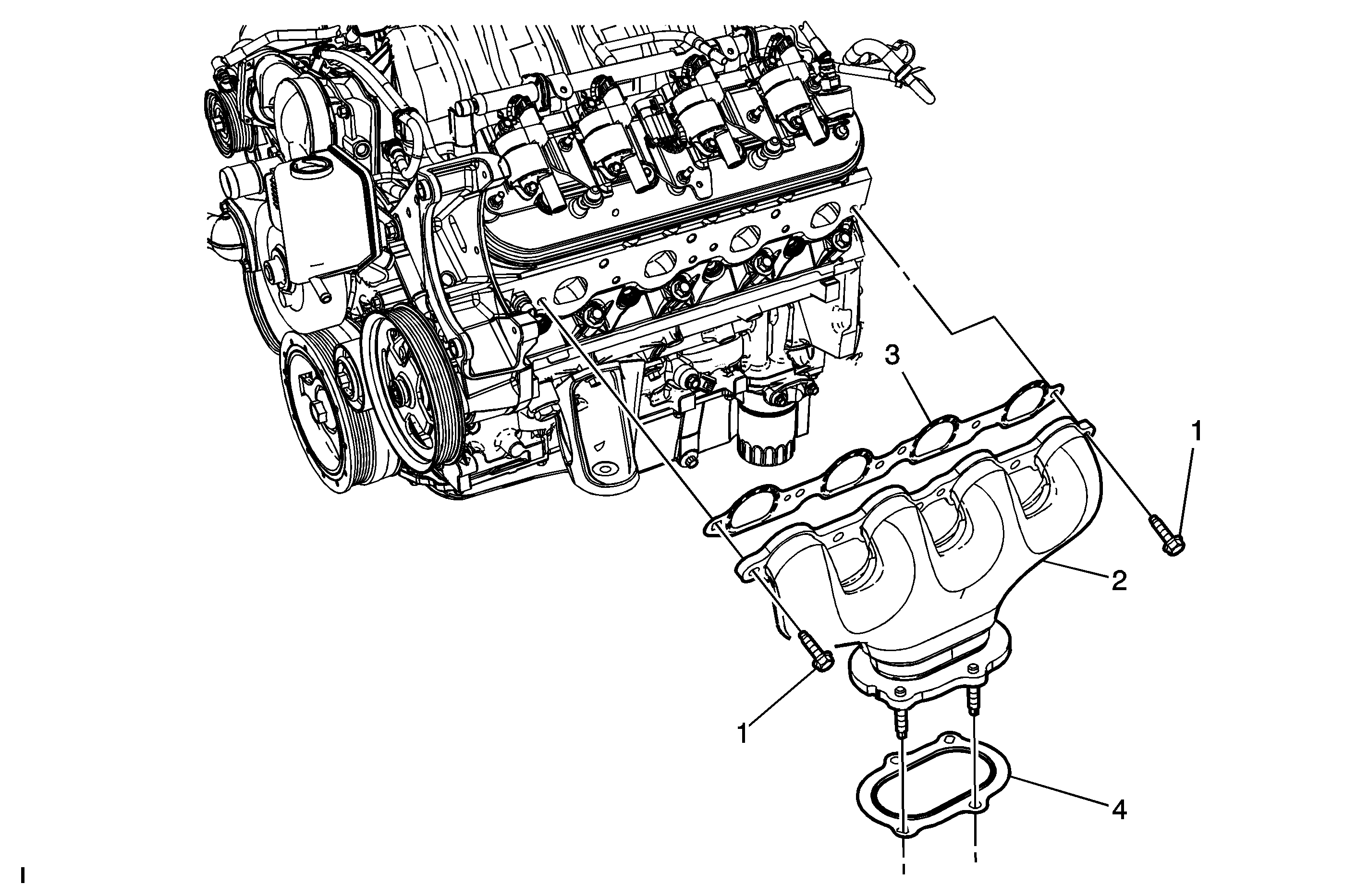
Exhaust Manifold Replacement - Left Side 7.0L

Callout | Component Name | ||||||||||
|---|---|---|---|---|---|---|---|---|---|---|---|
|
Notice: Refer to Excessive Force and Oxygen Sensor Notice in the Preface section. Preliminary Procedure
| |||||||||||
1 | Exhaust Manifold Bolt (Qty: 6) Notice: Refer to Fastener Notice in the Preface section. Procedure
Tighten
| ||||||||||
2 | Exhaust Manifold | ||||||||||
3 | Exhaust Manifold Gasket Tip | ||||||||||
4 | Exhaust Manifold Pipe Gasket Tip | ||||||||||
