Oil Cooler Hose/Pipe Replacement Front
Tools Required
| • | J 28467-B Universal Engine Support Fixture |
| • | J 38185 Spring Hose Clamp Pliers |
| • | J 41803 Engine Support Fixture |
| • | J 44827 Transmission Cooler Quick Disconnect |
Removal Procedure
- Position the front wheels straight ahead, remove the ignition key to lock the steering column.
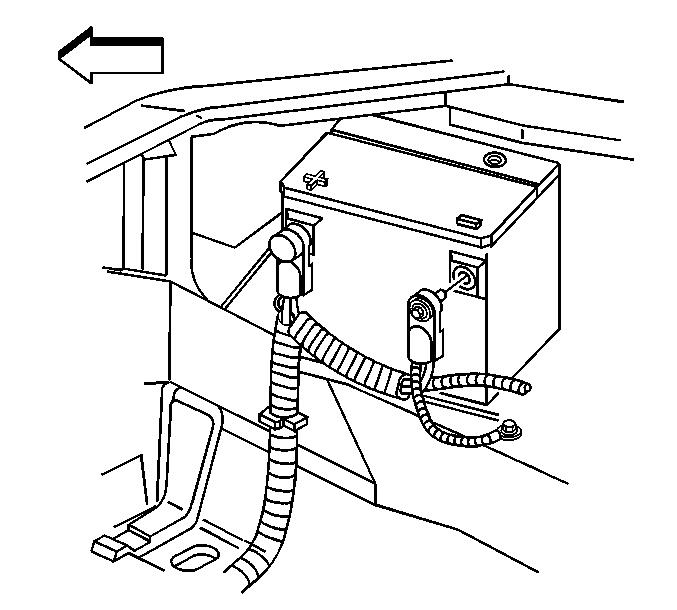
- Disconnect the negative battery cable. Refer to Battery Negative Cable Disconnection and Connection in Engine Electrical.
- Drain the cooling system. Refer to Cooling System Draining and Filling in Engine Cooling.
- Raise and suitably support the vehicle. Refer to Lifting and Jacking the Vehicle in General Information.
- Place a drain pan under the vehicle to catch any fluid.
- Reposition the plastic retainer, in order to gain access to the lower transmission oil cooler (TOC) connection.
- Using J 44827 , disconnect the lower TOC line from the oil cooler.
- Lower the vehicle; leave the vehicle on the hoist.
- Reposition the plastic retainer, in order to gain access to the upper TOC connection.
- Using J 44827 disconnect the upper TOC line from the oil cooler.
- Remove the air cleaner assembly. Refer to Air Cleaner Assembly Replacement in Engine Controls - 5.7L.
- Remove the upper and lower radiator support. Refer to Radiator Support Replacement in Engine Cooling.
- Recover the refrigerant from the air conditioning (A/C) system. Refer to Refrigerant Recovery and Recharging in Heating, Ventilation, and Air Conditioning.
- Remove the front evaporator tube to condenser bolt.
- Disconnect the front evaporator tube from the condenser.
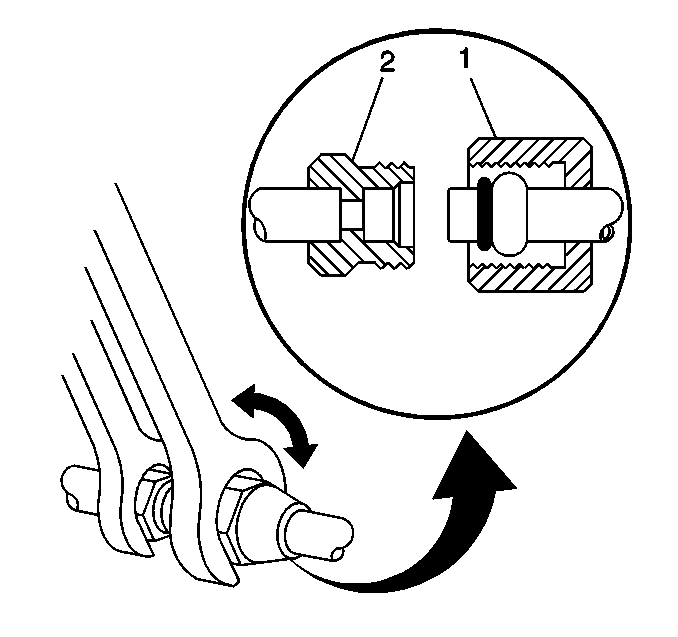
- Using a back-up wrench on the condenser fitting (2), loosen the compressor hose fitting (1) from the condenser.
- Disconnect the compressor hose from the condenser.
- Discard the O-ring seal and cap or tape the compressor hose and condenser openings.
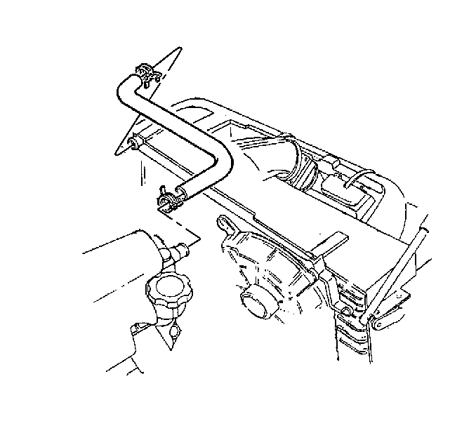
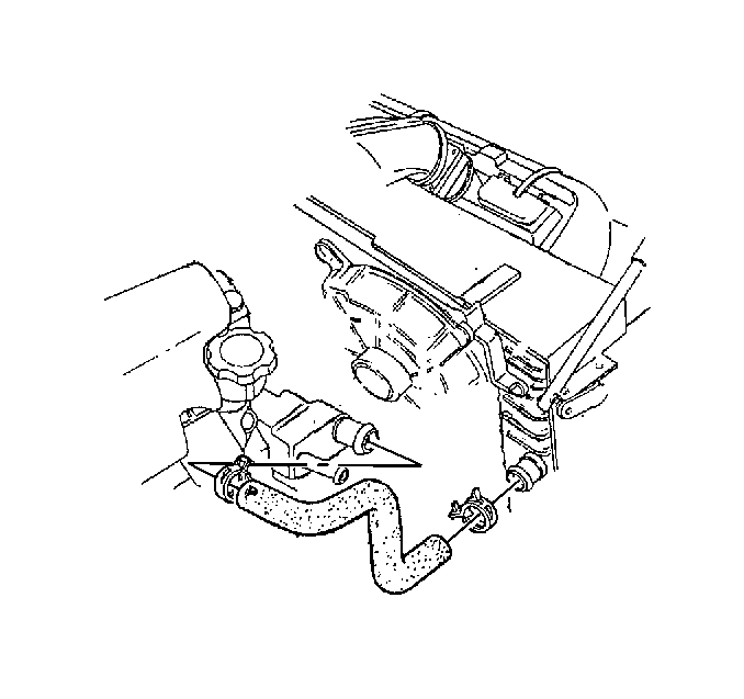
- Using J 38185 , release and reposition the coolant surge tank upper hose clamp away from the radiator inlet.
- Separate the surge tank upper hose from the radiator inlet.
- Using J 38185 , release and reposition the radiator inlet hose clamp away from the radiator inlet.
- Separate the radiator inlet hose from the radiator inlet.
- Using J 38185 , release and reposition the radiator outlet hose clamp away from the radiator outlet.
- Separate the radiator outlet hose from the radiator outlet.
- Carefully pivot the A/C condenser with the radiator forward and tie off to support the assembly.
- Remove the steering column intermediate shaft lower coupling shield.
- Match-mark the intermediate shaft lower coupling to the power steering (PS) gear to ensure correct orientation upon installation.
- Remove the intermediate shaft lower coupling bolt.
- Disconnect the intermediate shaft lower coupling from the PS gear.
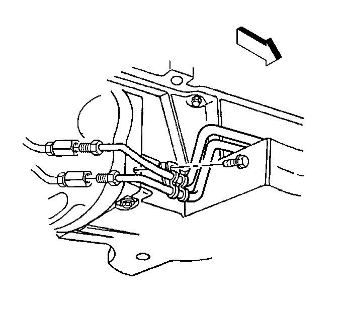
- Remove the PS cooler retaining bolts.
- Remove the brake pressure modulator valve (BPMV) bracket. Refer to Brake Pressure Modulator Valve Bracket Replacement in Antilock Brake System.
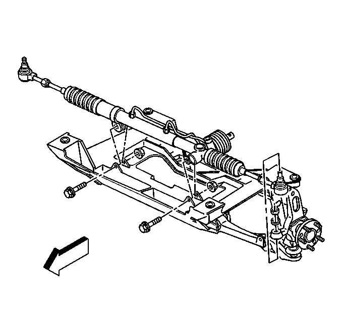
- Remove the PS gear mounting bolts and nuts.
- Release the PS gear and cooler from the front suspension crossmember, then slave the gear and cooler forward.
- Remove the A/C compressor bracket. Refer to Compressor Mounting Bracket Replacement in Heating, Ventilation, and Air Conditioning.
- Remove the generator. Refer to Generator Replacement in Engine Electrical.
- Install the J 41803 and the J 28467-B in order to support the engine.
- Remove the right hand engine mount (and bracket). Refer to Engine Mount Replacement - Right Side in Engine Mechanical - 5.7L.
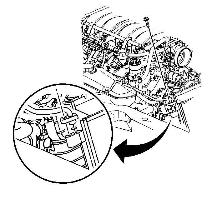
- Remove the TOC front pipe front clip.
- Raise the vehicle.
- Remove the TOC front pipe front retaining clamp bolt and retaining clamp.
- Remove the TOC front pipe rear retaining clamp bolt and retaining clamp.
- Disconnect the TOC front pipe fittings from the junction fittings at the engine flywheel housing, then cap the pipe fittings and plug the junction fittings to prevent contamination.
- Lower the vehicle; leave the vehicle slightly above the ground.
- Finesse the TOC front pipes out of the vehicle (through the top).

Important: Cap or tape the opening in the front evaporator tube and condenser immediately to prevent contamination.



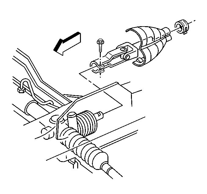
Slide the intermediate shaft lower coupling off of the PS gear steering shaft.



Installation Procedure
- Install the TOC front pipes to the vehicle (through the top of the vehicle).
- Raise the vehicle.
- Remove the caps from the rear of the TOC front pipes and remove the plugs from the junction fittings at the engine flywheel housing.
- ALIGN and HAND-START, then tighten ONLY by hand to seat the TOC front upper and lower pipe fittings to the junction fittings at the engine flywheel housing.
- Install the TOC front pipe rear retaining clamp and bolt.
- Install the TOC front pipe front retaining clamp and bolt.
- Install the TOC front pipe front clip.
- Install the right hand engine mount (and bracket). Refer to Engine Mount Replacement - Right Side in Engine Mechanical - 5.7L.
- Lower the vehicle; leave the vehicle on the hoist.
- Remove the J 41803 and the J 28467-B .
- Install the generator. Refer to Generator Replacement in Engine Electrical.
- Install the A/C compressor bracket. Refer to Compressor Mounting Bracket Replacement in Heating, Ventilation, and Air Conditioning.
- Position the PS gear and cooler to the front suspension crossmember.
- Install the BPMV bracket. Refer to Brake Pressure Modulator Valve Bracket Replacement in Antilock Brake System.
- Install the PS gear mounting bolts and nuts.
- Install the PS cooler retaining bolts.
- Connect the intermediate shaft lower coupling to the PS gear; be sure that the intermediate shaft and the PS gear steering shaft are orientated as marked prior to disconnecting them.
- Install the intermediate shaft lower coupling bolt.
- Install the intermediate shaft lower coupling shield.
- Lower the vehicle.
- Remove the tie-off retainer and carefully pivot the AC condenser and the radiator back into position.
- Install the radiator outlet hose to the radiator outlet.
- Using J 38185 , position the radiator outlet hose clamp onto the radiator outlet.
- Install the radiator inlet hose to the radiator inlet.
- Using J 38185 , position the radiator inlet hose clamp onto the radiator inlet.
- Install the surge tank upper hose to the radiator inlet.
- Using J 38185 , position the coolant surge tank upper hose clamp onto the radiator inlet.
- Install the compressor hose to the condenser.
- Using a back-up wrench on the condenser fitting (2), tighten the compressor hose fitting (1) to the condenser.
- Connect the front evaporator tube to the condenser.
- Install the front evaporator tube to condenser bolt.
- Install the upper and lower radiator support. Refer to Radiator Support Replacement in Engine Cooling.
- Install the air cleaner assembly. Refer to Air Cleaner Assembly Replacement in Engine Controls.
- Connect the upper TOC line to the oil cooler using the following steps:
- Position the plastic retainer over the connection.
- Raise the vehicle.
- Connect the lower TOC line to the oil cooler using the following steps:
- Position the plastic retainer over the connection.
- Lower the vehicle.
- Connect the negative battery cable.
- Fill the cooling system. Refer to Cooling System Draining and Filling in Engine Cooling.
- Recharge the AC system. Refer to Refrigerant Recovery and Recharging in Heating, Ventilation, and Air Conditioning.
- Check the transmission fluid level. Add if necessary.

Finesse the pipes into position.
Notice: Use the correct fastener in the correct location. Replacement fasteners must be the correct part number for that application. Fasteners requiring replacement or fasteners requiring the use of thread locking compound or sealant are identified in the service procedure. Do not use paints, lubricants, or corrosion inhibitors on fasteners or fastener joint surfaces unless specified. These coatings affect fastener torque and joint clamping force and may damage the fastener. Use the correct tightening sequence and specifications when installing fasteners in order to avoid damage to parts and systems.
Tighten
Tighten the transmission oil cooler front upper and lower pipe fittings
to the junction at the engine flywheel housing to 27 N·m (20 lb ft).
Tighten
Tighten the transmission oil cooler front pipe rear retaining clamp
bolt to 2.2 N·m (19 lb in).

Tighten
Tighten the transmission oil cooler front pipe front retaining clamp
bolt to 12 N·m (106 lb in).


Tighten
Tighten the power steering gear mounting nuts to 100 N·m
(74 lb ft).

Tighten
Tighten the power steering cooler retaining bolts to 11 N·m
(97 lb in).

Slide the intermediate shaft lower coupling onto the PS gear steering shaft.
Tighten
Tighten the steering column intermediate shaft lower coupling bolt to
34 N·m (25 lb ft).


Tighten
Tighten the fitting to 24 N·m (17 lb ft).

Tighten
Tighten the front evaporator tube bolt to 27 N·m (20 lb ft).

| 34.1. | Push the TOC pipe into the quick connect fitting, until a click is heard. |
| 34.2. | Tug gently in the TOC line to ensure a proper connection. |
| 37.1. | Push the TOC pipe into the quick connect fitting, until a click is heard. |
| 37.2. | Tug gently in the TOC line to ensure a proper connection. |

Tighten
Tighten the negative battery cable bolt to 15 N·m (11 lb ft).
Oil Cooler Hose/Pipe Replacement Rear
Removal Procedure
- Raise and suitably support the vehicle. Refer to Lifting and Jacking the Vehicle in General Information.
- Remove the catalytic converter. Refer to Catalytic Converter Replacement in Engine Exhaust.
- Remove the right side muffler. Refer to Exhaust Muffler Replacement - Right Side in Engine Exhaust.
- Remove the driveline tunnel closeout panel. Refer to Floor Panel Tunnel Panel Reinforcement Replacement in Propeller Shaft.
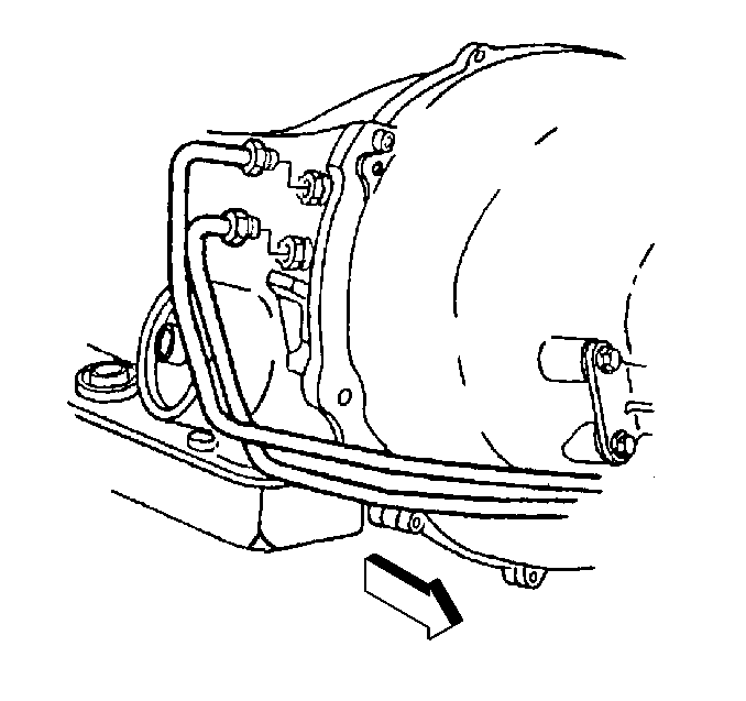
- Disconnect the transmission oil cooler (TOC) rear upper and lower pipe fittings from the junction fittings at the engine flywheel housing, then cap the pipes and plug the junction fittings to prevent contamination.
- Disconnect the TOC rear upper and lower pipe fittings from the transmission fittings, then cap the pipes and plug the transmission fittings to prevent contamination.
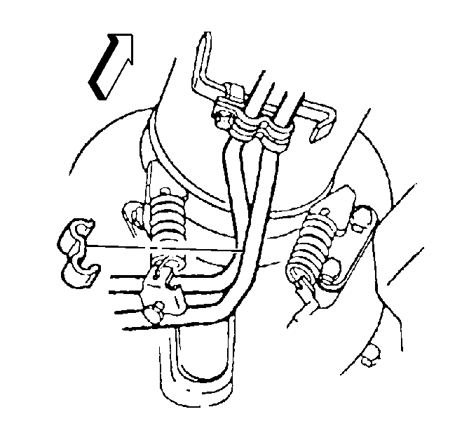
- Remove the TOC rear pipe rear clip.
- Remove the TOC rear pipe middle clip.
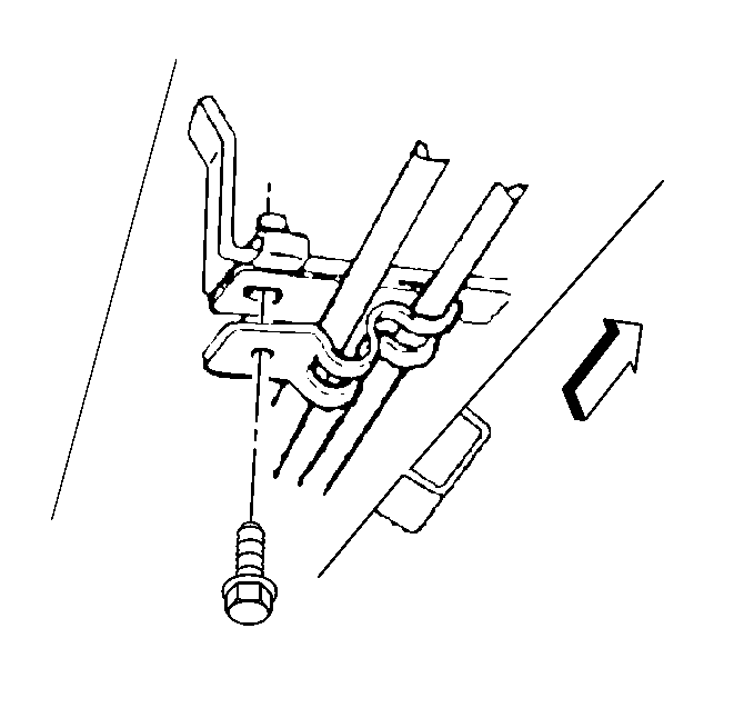
- Remove the TOC rear pipe front and rear clamp bolts and clamps.
- Remove the TOC rear pipes from the vehicle.

Installation Procedure
- Install the transmission oil cooler (TOC) rear pipes into position.
- Install the TOC rear pipe front and rear retaining clamps and bolts.
- Install the TOC rear pipe middle clip.
- Install the TOC rear pipe rear clip.
- Remove the caps from the rear of the TOC rear pipes and remove the plugs from the transmission fittings.
- ALIGN and HAND-START, then tighten ONLY by hand to seat the TOC rear upper and lower pipe fittings to the transmission fittings.
- ALIGN and HAND-START, then tighten ONLY by hand to seat the TOC rear upper and lower pipe fittings to the junction fittings at the engine flywheel housing.
- Install the driveline tunnel closeout panel. Refer to Floor Panel Tunnel Panel Reinforcement Replacement in Propeller Shaft.
- Install the right side muffler. Refer to Exhaust Muffler Replacement - Right Side in Engine Exhaust.
- Install the catalytic converter. Refer to Catalytic Converter Replacement in Engine Exhaust.
- Check the transmission fluid level. Add if necessary.
- Lower the vehicle.

Notice: Use the correct fastener in the correct location. Replacement fasteners must be the correct part number for that application. Fasteners requiring replacement or fasteners requiring the use of thread locking compound or sealant are identified in the service procedure. Do not use paints, lubricants, or corrosion inhibitors on fasteners or fastener joint surfaces unless specified. These coatings affect fastener torque and joint clamping force and may damage the fastener. Use the correct tightening sequence and specifications when installing fasteners in order to avoid damage to parts and systems.
Tighten
Tighten the transmission oil cooler rear pipe front and rear retaining
clamp bolts to 12 N·m (106 lb in).


Tighten
Tighten the transmission oil cooler rear upper and lower pipe fittings
to the transmission fittings to 35 N·m (26 lb ft).

Tighten
Tighten the transmission oil cooler rear upper and lower pipe fittings
to the junction fittings at the engine flywheel housing to 27 N·m
(20 lb ft).
