Fuel Sender Assembly Replacement W/O FFS
Tools Required
| • | J 37088-A Tool
Set, Fuel Line Quick Connect Separator |
Removal Procedure (Left or Right)
Caution: Unless directed otherwise, the ignition and start switch must be in the OFF or LOCK position, and all electrical loads must be OFF before servicing
any electrical component. Disconnect the negative battery cable to prevent an electrical spark should a tool or equipment come in contact with an exposed electrical terminal. Failure to follow these precautions may result in personal injury and/or damage to
the vehicle or its components.
- Disconnect the negative battery cable.
- Relieve the fuel system pressure. Refer to the
Fuel Pressure Relief
.
Caution: To avoid any vehicle damage, serious personal injury or death when major components are removed from the vehicle and the vehicle is supported by a
hoist, support the vehicle with jack stands at the opposite end from which the components are being removed and strap the vehicle to the hoist.
- Raise the vehicle. Refer to
Lifting and Jacking the Vehicle
in General Information.
- Remove the rear wheel and tire assembly. Refer to
Tire and Wheel Removal and Installation
in Tires and Wheels.
- Clean all of the fuel connections and the surrounding areas before disconnecting
the fuel pipes in order to avoid possible contamination of the fuel system.
- Drain the fuel tanks. Refer to
Fuel Tank Draining
.
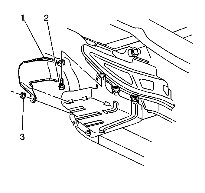
- Remove the fuel tank shield.
- Mark or identify each fuel pipe in order to aid in installing the pipes
in their original positions.
- Disconnect the quick-connect fittings from the fuel sender. Refer to
Plastic Collar Quick Connect Fitting Service
.
- Cap all of the fuel pipes.
- Disconnect the fuel sender electrical connector.
- Remove the fuel tank strap.
- Support the fuel tank.
- Remove the fuel sender attaching bolts.
- Remove the float arm retaining clip and the float arm for the left fuel
sender only.
- Carefully remove the fuel sender with the gasket.
- Clean the gasket sealing surfaces.
Installation Procedure (Right)
- Inspect the fuel sender gasket for damage and replace if necessary.

Important: Do not bend or twist the float arm.
- Insert the float arm through the fuel tank opening.
- The fuel sender may need to be rotated in order to facilitate the installation.
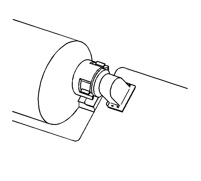
- Align the fuel sender gasket tab (2) with the fuel sender cover
mark (1).
- Align the fuel sender cover mark (1) with the fuel tank mark.

- Hand tighten the fuel sender attaching bolts until finger tight.
Notice: Refer to Fastener Notice in the Preface section.
- Tighten the fuel sender assembly attaching bolts in sequence.
Tighten
Tighten the bolt to 7 N·m (62 lb in).
- Connect the fuel sender fuel feed pipe (1) (from the jet pump
to the left tank, and the fuel feed rear crossover pipe (2) from the left
tank to the jet pump). Refer to
Plastic Collar Quick Connect Fitting Service
.

- Connect the fuel sender electrical connector.


- Install the fuel tank strap (3).
- Install the fuel tank strap bolts (1, 2, 4).
Tighten
| • | Tighten the bolt (2) to 25 N·m (18 lb ft). |
| • | Tighten the bolt (1) to 25 N·m (18 lb ft). |
| • | Tighten the remaining bolts (4) to 25 N·m (18 lb ft). |

- Install the fuel tank shield (1).
- Install the fuel tank shield mount bolt (2).
- Install the fuel tank shield mount nut (3).
Tighten
| • | Tighten the fuel tank shield mount bolt to 25 N·m (18 lb ft). |
| • | Tighten the fuel tank shield mount nut to 12 N·m (106 lb in). |
- Install the rear wheel and tire assembly. Refer to
Tire and Wheel Removal and Installation
in Tires and Wheels.
- Lower the vehicle.
- Refill the fuel system.
- Install the fuel filler cap.
- Connect the negative battery cable.
- Perform the following procedure in order to inspect for leaks:
| 20.1. | Turn the ignition switch ON for 2 seconds. |
| 20.2. | Turn the ignition switch OFF for 10 seconds. |
| 20.3. | Turn the ignition switch ON. |
| 20.4. | Inspect for fuel leaks. |
- Program the transmitters. Refer to
Transmitter Programming
in Keyless Entry.
Installation Procedure (Left)

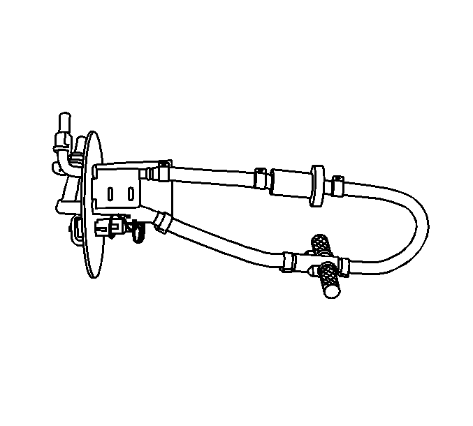
- Install fuel pump strainer in the same position
as noted during disassembly. Push on the outer edge of the strainer ferrule until
the strainer is fully seated.
- Install a sender gasket on the fuel sender.
- Insert the fuel sender through the fuel tank opening.
- The fuel sender may need to be rotated in order to facilitate the installation.
Important: Do not bend or twist the float arm.
- Insert the float and the float arm into the fuel tank opening.
- Install the float arm retaining clip.

- Align the fuel sender gasket tab (1)
with the fuel sender cover mark (2).
- Align the fuel sender cover mark (2) with the fuel tank mark.
- Tighten the fuel sender attaching bolts until the bolts are finger
tight.

- Tighten the fuel sender assembly attaching
bolts in proper sequence.
Tighten
Tighten bolts to 7 N·m (62 lb in).

- Connect the fuel sender fuel feed pipe (1)
from the jet pump to the left tank, to the fuel return rear pipe (2), and
to the fuel feed rear pipe (3). Refer to
Plastic Collar Quick Connect Fitting Service
.
- Connect the fuel sender electrical connector.

- Install the fuel tank strap (3).
- Install the fuel tank strap bolts (1, 2, 4).
Tighten
| • | Tighten the bolt (2) to 25 N·m (18 lb ft). |
| • | Tighten the bolt (1) to 25 N·m (18 lb ft). |
| • | Tighten the remaining bolts (4) to 25 N·m (18 lb ft). |

- Install the fuel tank shield (1).
- Install the fuel tank shield mount bolt (2).
- Install the fuel tank shield mount nut (3).
Tighten
| • | Tighten the fuel tank shield mount bolt to 25 N·m (18 lb ft). |
| • | Tighten the fuel tank shield mount nut to 12 N·m (106 lb in). |
- Install the rear wheel and tire assembly. Refer to
Tire and Wheel Removal and Installation
in Tires and Wheels.
- Lower the vehicle.
- Refill the fuel system.
- Install the fuel filler cap.
- Connect the negative battery cable.
- Perform the following procedure in order to inspect for leaks:
| 23.1. | Turn the ignition switch ON for 2 seconds. |
| 23.2. | Turn the ignition switch OFF for 10 seconds. |
| 23.3. | Turn the ignition switch ON. |
| 23.4. | Inspect for fuel leaks. |
- Program the transmitters. Refer to
Transmitter Programming
in Keyless Entry.


