For 1990-2009 cars only
Removal Procedure
- Raise and support the vehicle. Refer to Lifting and Jacking the Vehicle in General Information.
- Remove the tire and wheel assembly. Refer to Tire and Wheel Removal and Installation in Tires and Wheels.
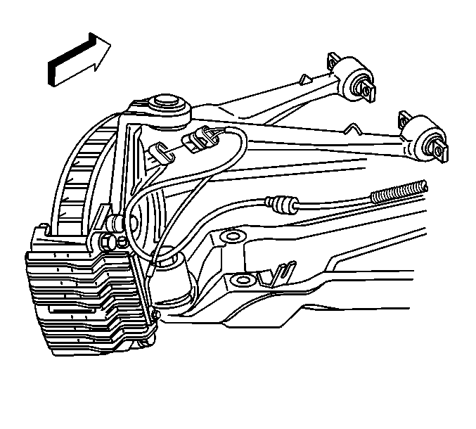
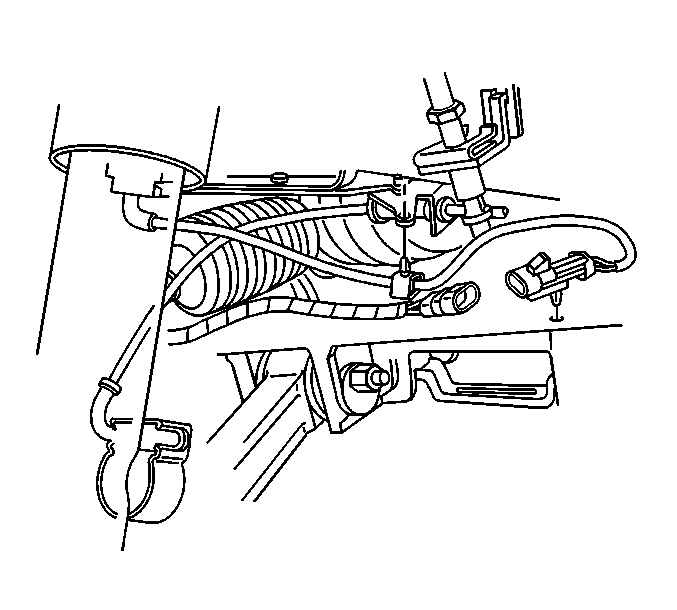
- Disconnect the wheel speed sensor electrical connector.
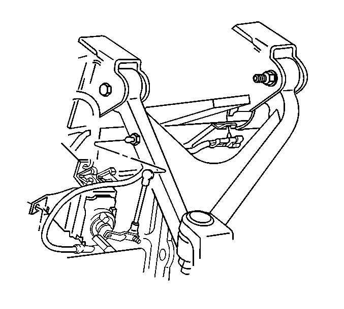
- Disconnect the real time damping (RTD) position sensor link, if equipped.
- Remove the brake rotor. Refer to Rear Brake Rotor Replacement in Disc Brakes.
- Remove the shock absorber solenoid electrical connector, if equipped.
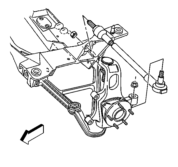
- Separate the outer tie rod end from the suspension knuckle. Refer to Tie Rod Replacement .
- Remove the spindle nut retainer, the spindle nut and the washer. Refer to Wheel Drive Shaft Replacement in Wheel Drive Shafts.
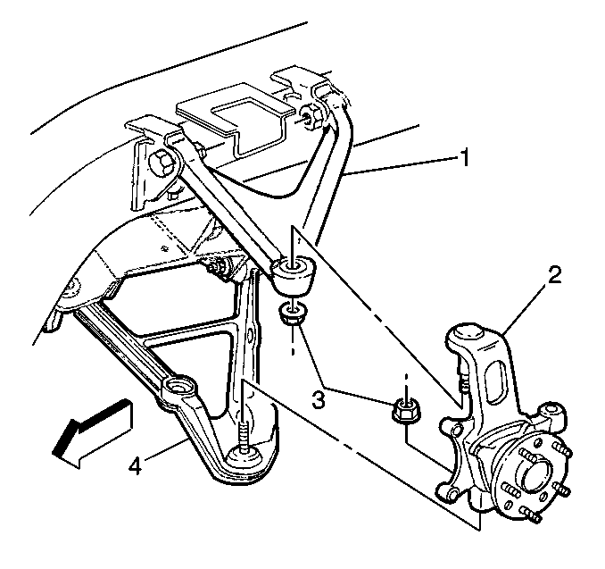
- Separate the suspension knuckle (2) from the upper control arm (1). Refer to Rear Axle Upper Control Arm Replacement .
- Separate the suspension knuckle (2) from the lower control arm ball joint stud (4). Refer to Rear Axle Lower Control Arm Replacement .
- Remove the suspension knuckle.
Installation Procedure
- Install the suspension knuckle (2) to the lower control arm (4) ball joint stud. Refer to Rear Axle Lower Control Arm Replacement .
- Install the suspension knuckle ball joint stud (2) to the upper control arm (1). Refer to Rear Axle Upper Control Arm Replacement .
- Install the spindle nut, washer and retainer. Refer to Wheel Drive Shaft Replacement in Wheel Drive Shafts.
- Install the outer tie rod end to the suspension knuckle. Refer to Tie Rod Replacement .
- Install the brake rotor and caliper. Refer to Rear Brake Caliper Bracket Replacement and Front Brake Rotor Replacement in Disc Brakes.
- Connect the wheel speed sensor electrical connector.
- Install the shock absorber solenoid electrical connector, if equipped.
- Connect the real time damping position sensor link, if equipped.
- Install the tire and wheel assembly. Refer to Tire and Wheel Removal and Installation in Tires and Wheels.
- Lower the vehicle.
- Perform a rear wheel alignment. Refer to Wheel Alignment Measurement in Wheel Alignment.

