Seat Belt Retractor Anchor Plate Replacement Convertible
Removal Procedure
- Lower the folding top.
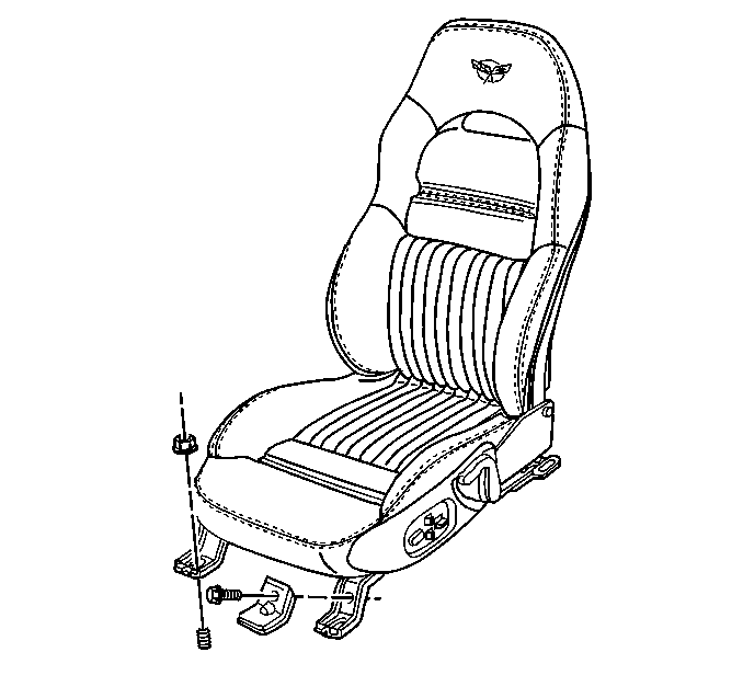
- Remove the seat. Refer to Seat Replacement (Power) or Seat Replacement (Manual) in Seats.
- Remove the upper lock pillar trim. Refer to Body Lock Pillar Trim Panel Replacement in Interior Trim.
- Remove the lower lock pillar trim. Refer to Body Lock Pillar Trim Panel Replacement in Interior Trim.
- Partially remove the intermediate carpet.
- Remove the ground wire bolt and reposition the wires (LH side only).
- Reposition the wire harness.
- Install a protective cover to the interior.
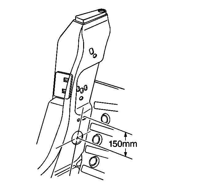
- Drill a 38.1 mm (1.5 in) access hole 150 mm (6 in) in the lock pillar below the lower gauge slot on a line parallel to the lock pillar.
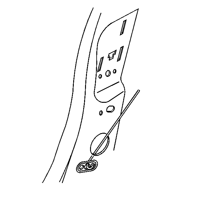
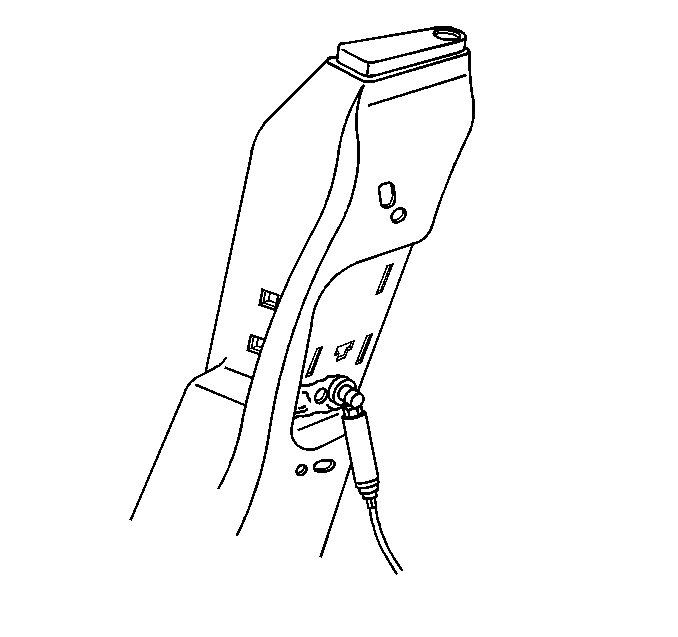
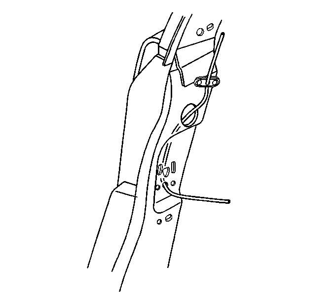
- insert a wire through the anchor plate and down out through the drilled hole.
- Locate the anchor plate weld witness marks on the pillar.
- Drill out the spot welds that are attaching the anchor plate.
- Allow the anchor plate to slide down the wire to the drilled hole.
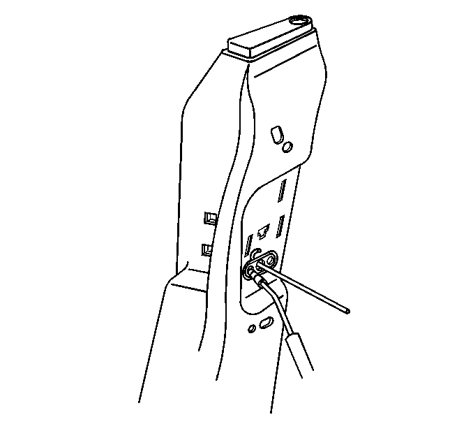
- Insert a hooked rod through the drilled out hole and hook the anchor plate.
- Remove the anchor plate through the drilled hole.
- Remove the wire.

Installation Procedure
- Remove the folding top stowage lid bumper from the top of the lock pillar.
- Route a long stiff wire down through the bumper hole and out through the drilled out hole.
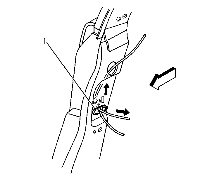
- Attach a new seat belt anchor plate to the stiff wire.
- Pull the stiff wire with the anchor plate attached through the drilled out hole upward to the hole where the plate attaches.
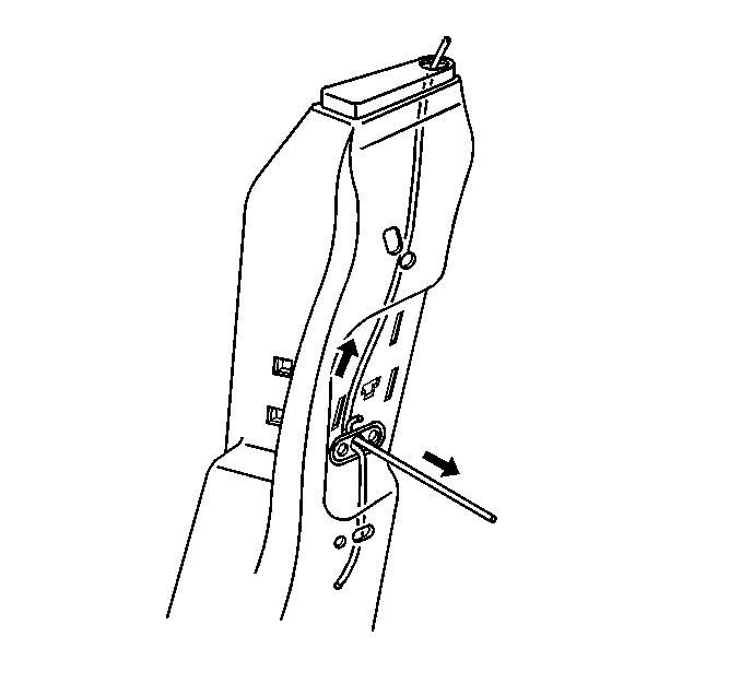
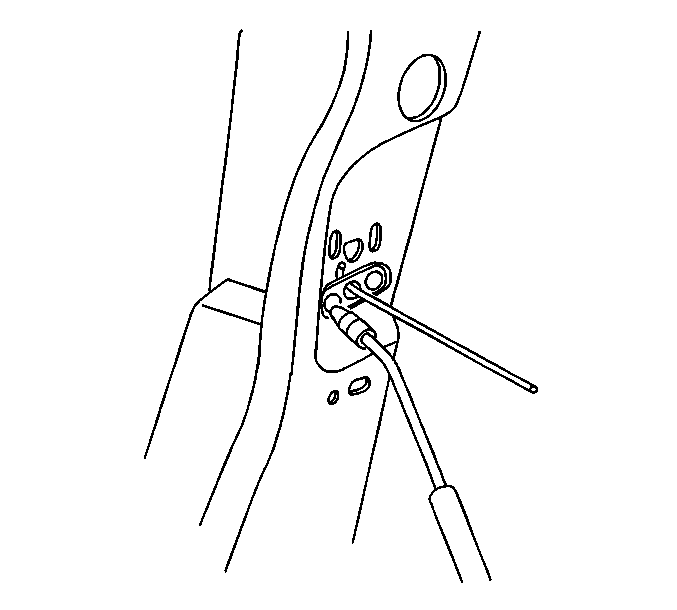
- Insert a hooked rod through the bolt hole in the pillar and hook the anchor plate.
- Pull the anchor plate into position against the inside of the lock pillar.
- Push the stiff wire down and remove the stiff wire through the drilled hole.
- Pull the anchor plate into position tight against the inside of the lock pillar.
- Mig weld the anchor plate into position welding both ends of the anchor plate to the pillar.
- Remove the hooked rod.
- Grind smooth the welded surface.
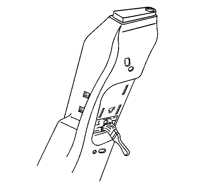
- Apply primer to the repaired area.
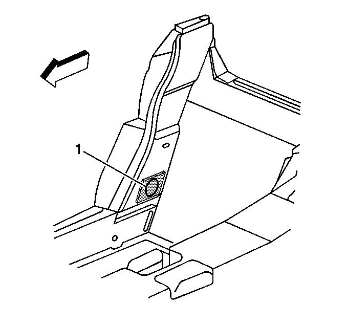
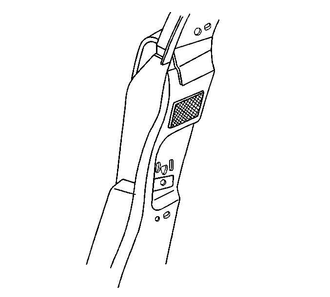
- Cover the drilled hole (1) with a sealing patch.
- Remove the protective cover from the interior of the vehicle.
- Reposition the ground wires and install the ground bolt.
- Reposition the wire harness.
- Install the intermediate carpet.
- Install the lock pillar lower trim. Refer to Body Lock Pillar Trim Panel Replacement in Interior Trim.
- Install the lock pillar upper trim. Refer to Body Lock Pillar Trim Panel Replacement in Interior Trim.
- Install the stowage lid bumper.
- Install the seat. Refer to Seat Replacement (Power) or Seat Replacement (Manual) in Seats.
- Raise and secure the folding top.
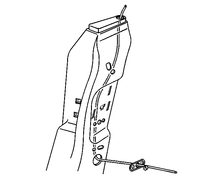
| 3.1. | Insert the wire through the threaded hole in the anchor plate. |
| 3.2. | Slide the plate up the wire. |
| 3.3. | Make a small loop in the wire so the anchor plate can not side back down the wire. |
Caution: To avoid personal injury when exposed to welding flashes or to galvanized (Zinc Oxide) metal toxic fumes while grinding/cutting on any type of metal or sheet molded compound, you must work in a properly ventilated area, wearing an approved respirator, eye protection , earplugs, welding gloves, and protective clothing.
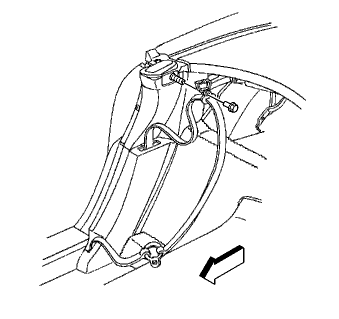
Notice: Use the correct fastener in the correct location. Replacement fasteners must be the correct part number for that application. Fasteners requiring replacement or fasteners requiring the use of thread locking compound or sealant are identified in the service procedure. Do not use paints, lubricants, or corrosion inhibitors on fasteners or fastener joint surfaces unless specified. These coatings affect fastener torque and joint clamping force and may damage the fastener. Use the correct tightening sequence and specifications when installing fasteners in order to avoid damage to parts and systems.
Tighten
Tighten the antenna ground bolt to 5.8 N·m (51 lb in).
Seat Belt Retractor Anchor Plate Replacement Coupe, Hardtop
Removal Procedure
- Remove the seat. Refer to Seat Replacement in Seats.
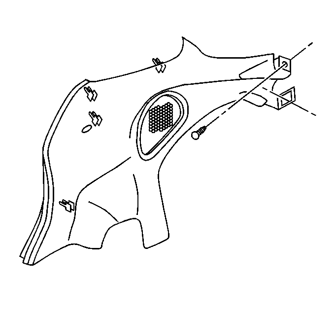
- Remove the rear compartment front side trim panel. Refer to Rear Compartment Side Trim Panel Replacement in Interior Trim.
- Partially remove the intermediate carpet.
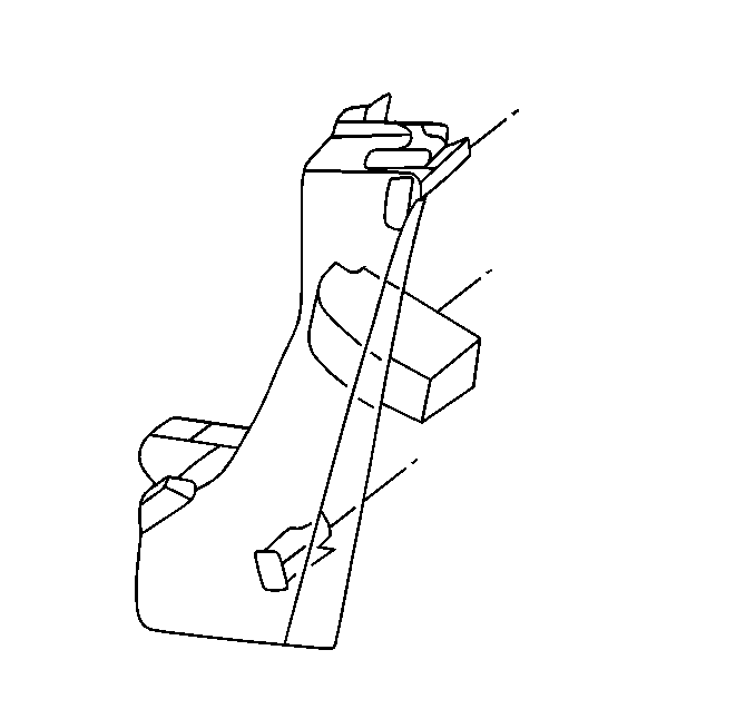
- Remove the lower lock pillar trim. Refer to Body Lock Pillar Trim Panel Replacement in Interior Trim.
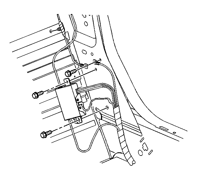
- Remove the ground wire bolt and ASR module from the left side only.
- Reposition the wire harness.
- Reposition the seat belt.
- Install a protective cover over the interior trim of the vehicle.
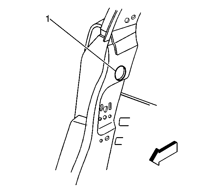
- Drill a 38 mm (1.5 in) hole (1) in the lock pillar above the upper retractor anchor plate as shown.
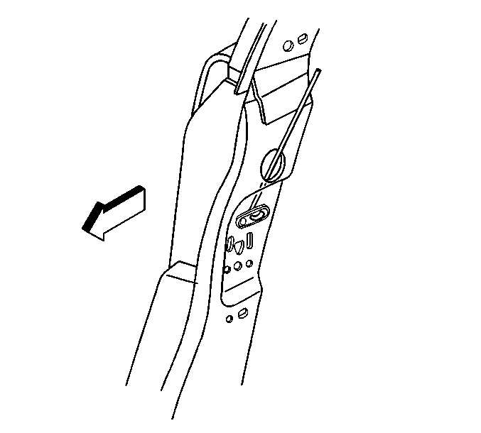
- Insert a rod down through the drilled out hole and out through the anchor plate.
- Bend a hook on the end of the rod.
- Hook the anchor plate.
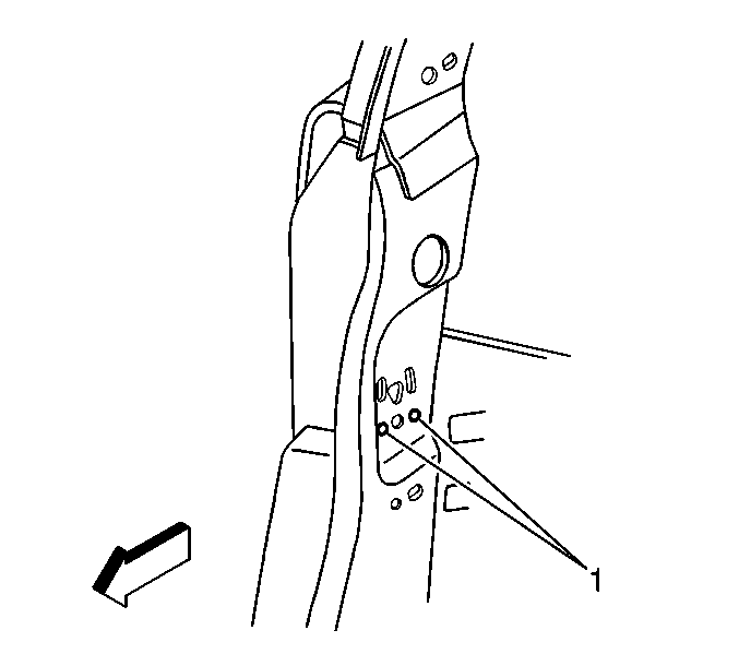
- Locate the anchor plate spot weld witness marks on the lock pillar.
- Drill out the spot welds (1) that are securing the anchor plate to the lock pillar.
- Remove the anchor plate with the hooked rod up through the drilled out hole.
Installation Procedure
- Insert a stiff wire down through the drilled out hole and out through the anchor plate hole.
- Place the new anchor plate, flat side first, onto the stiff wire and allow the plate to slide downward to the anchor plate hole.
- Insert a hooked rod through the anchor plate hole.
- Hook the anchor plate (1).
- Align the plate to the lock pillar opening.
- Pull the plate tight against the inside of the lock pillar.
- Mig weld the anchor plate into position welding both ends of the anchor plate to the pillar.
- Remove the stiff wire and the hooked rod.
- Grind smooth the welded surface.
- Apply primer to the repaired area.
- Cover the drilled hole with a sealing patch.
- Remove the protective cover from the interior of the vehicle.
- Reposition the ground wires and install the ground bolt on the left side only.
- Install the intermediate carpet.
- Install the bolt attaching the upper seat belt retractor to the new anchor plate.
- Install the lock pillar lower trim. Refer to Body Lock Pillar Trim Panel Replacement in Interior Trim.
- Install the rear compartment front side trim panel. Refer to Rear Compartment Side Trim Panel Replacement in Interior Trim.
- Install the seat. Refer to Seat Replacement in Seats.
Caution: To avoid personal injury when exposed to welding flashes or to galvanized (Zinc Oxide) metal toxic fumes while grinding/cutting on any type of metal or sheet molded compound, you must work in a properly ventilated area, wearing an approved respirator, eye protection , earplugs, welding gloves, and protective clothing.



Notice: Use the correct fastener in the correct location. Replacement fasteners must be the correct part number for that application. Fasteners requiring replacement or fasteners requiring the use of thread locking compound or sealant are identified in the service procedure. Do not use paints, lubricants, or corrosion inhibitors on fasteners or fastener joint surfaces unless specified. These coatings affect fastener torque and joint clamping force and may damage the fastener. Use the correct tightening sequence and specifications when installing fasteners in order to avoid damage to parts and systems.
Tighten
Tighten the antenna ground bolt to 5.8 N·m (51 lb in).
Tighten
Tighten the bolt to 41 N·m (31 lb ft).
