Removal Procedure
- Remove the console. Refer to Console Replacement in Instrument Panel, Gages and Console.
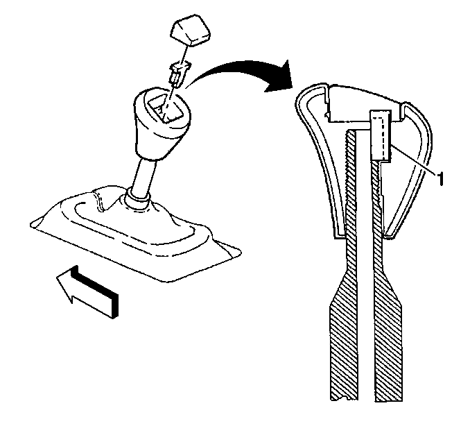
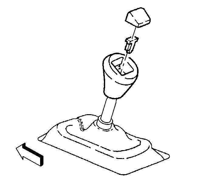
- Carefully pry off the shift control knob button.
- Pry the shift control knob retainer out of the slots and remove the retainer.
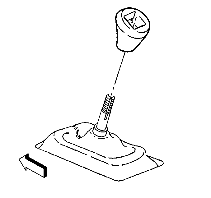
- Unscrew the shift control knob.
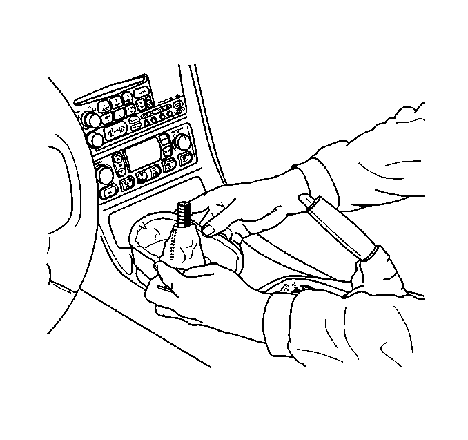
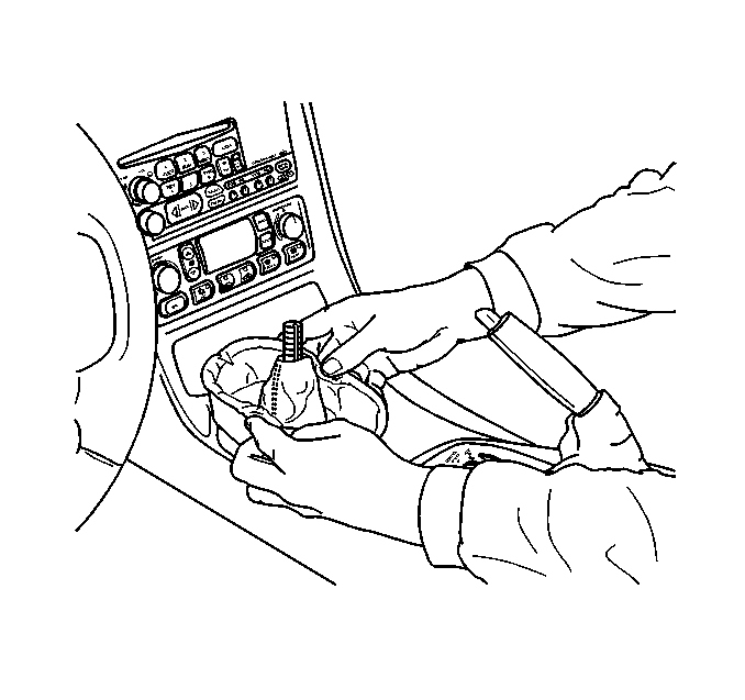
- Grasp the sides of the shift control boot and apply light pressure in toward the shift control lever to begin to release the shift boot retaining tabs from the IP accessory trim plate.
- Using light pressure, continue to release the remaining boot retaining tabs.
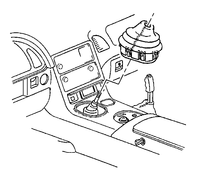
- Lift the boot away from the trim plate and remove the boot.
- Remove the IP accessory trim plate. Refer to Instrument Panel Accessory Trim Plate Replacement in Instrument Panel, Gages and Console.
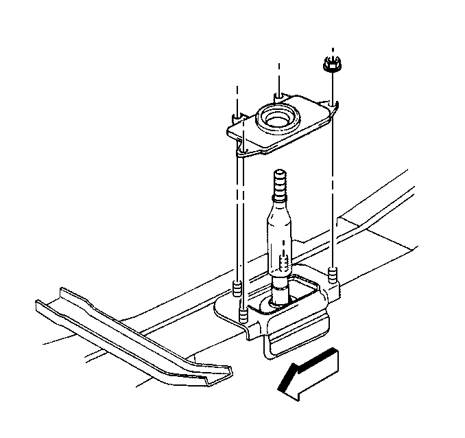
- Remove the shift control closeout boot retaining nuts.
- Remove the shift control closeout boot.
Installation Procedure
- Install the shift control closeout boot.
- Install the shift control closeout boot retaining nuts.
- Install the IP accessory trim plate. Refer to Instrument Panel Accessory Trim Plate Replacement in Instrument Panel, Gages and Console.
- Install the shift control boot over the shift control lever.
- Align the shift control boot to the IP accessory trim plate opening, then press to lock the boot retaining tabs.
- Adjust the shape of the boot for appearance, if necessary.
- Screw the shift control knob onto the shift control lever until the knob bottoms out.
- Unscrew the shift control knob just enough to align the retainer slot with the slot on the shift control lever.
- Install the shift control knob retainer (1) into the slots and seat fully.
- Install the shift control knob button.
- Install the console. Refer to Console Replacement in Instrument Panel, Gages and Console.
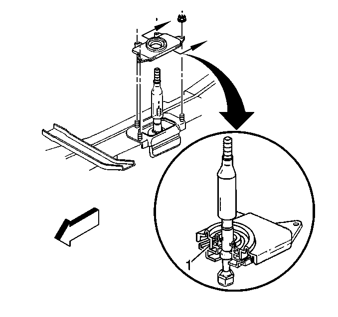
Check that the closeout boot fully seats to the shift control lever seal and the base of the shift control assembly (1).
Notice: Use the correct fastener in the correct location. Replacement fasteners must be the correct part number for that application. Fasteners requiring replacement or fasteners requiring the use of thread locking compound or sealant are identified in the service procedure. Do not use paints, lubricants, or corrosion inhibitors on fasteners or fastener joint surfaces unless specified. These coatings affect fastener torque and joint clamping force and may damage the fastener. Use the correct tightening sequence and specifications when installing fasteners in order to avoid damage to parts and systems.
Tighten
Tighten the shift control closeout boot retaining nuts to 12 N·m
(106 lb in).

