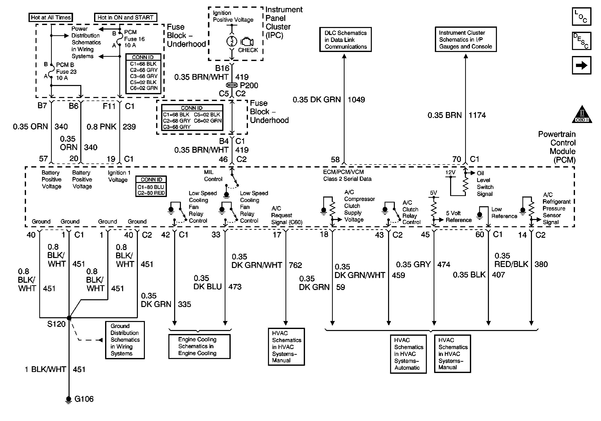
| Figure 1: |
Power, Ground, DLC, MIL Control, Engine Cooling and HVAC
|
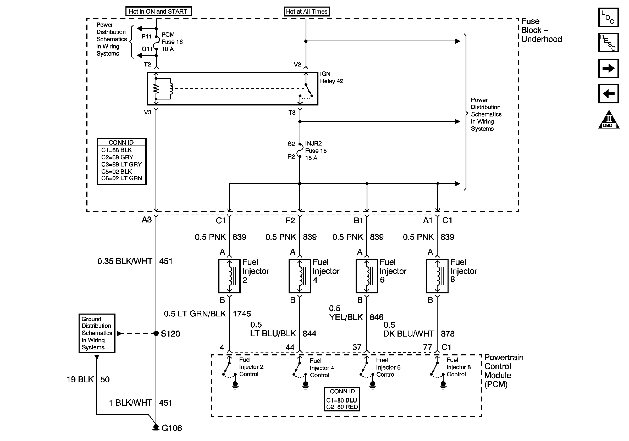
| Figure 2: |
Fuel Injectors 2, 4, 6 and 8
|
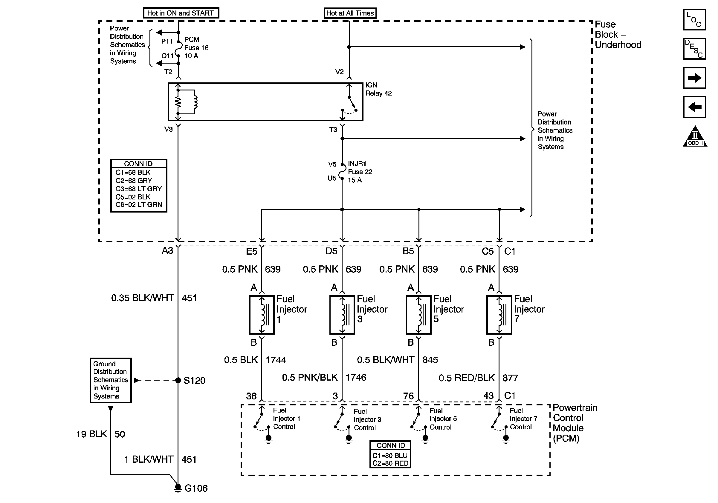
| Figure 3: |
Fuel Injectors 1, 3, 5 and 7
|
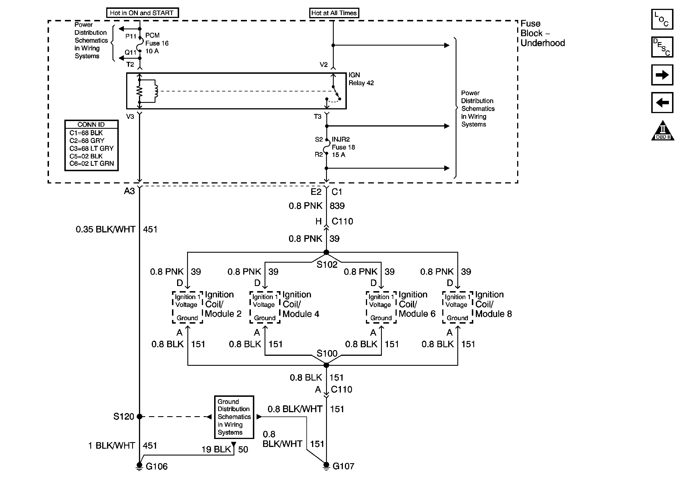
| Figure 4: |
Ignition Coil/Modules 2, 4, 6 and 8 Power and Ground
|
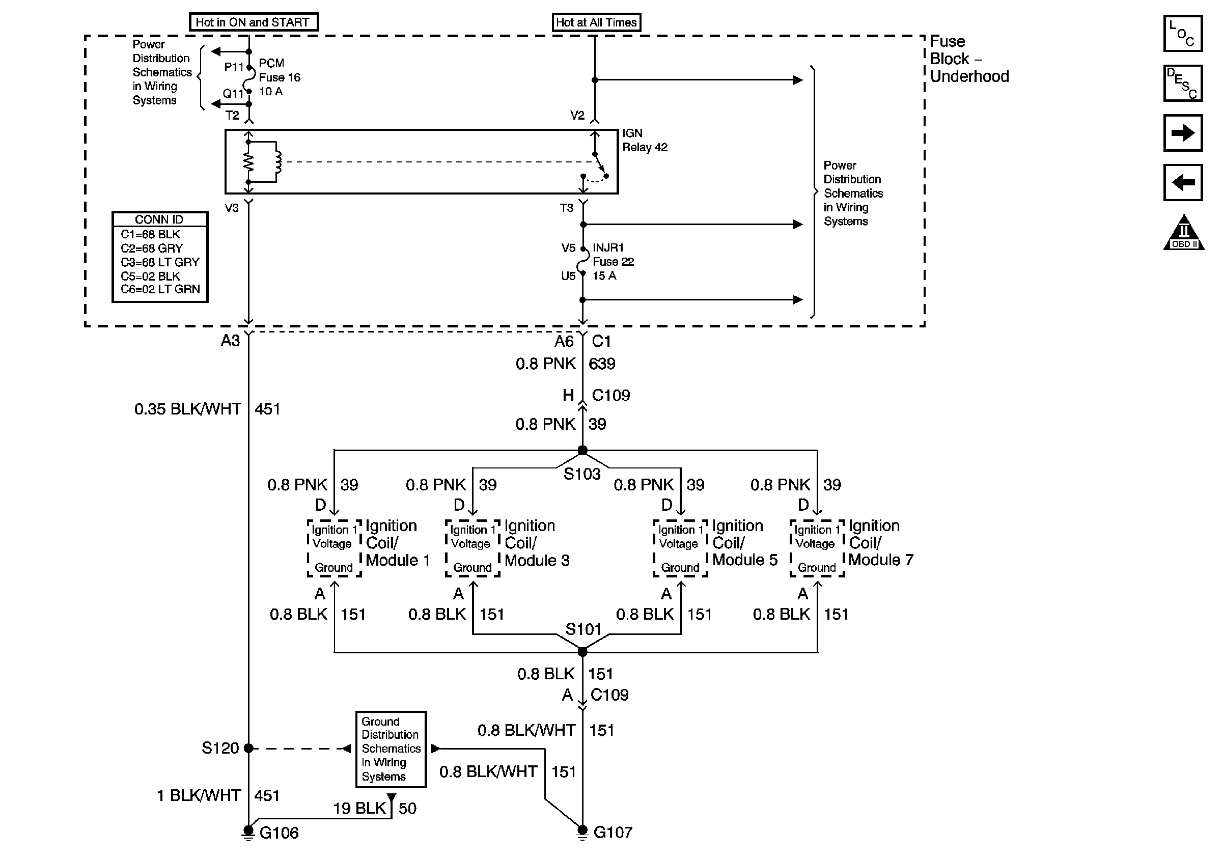
| Figure 5: |
Ignition Coil/Modules 1, 3, 5 and 7 Power and Ground
|
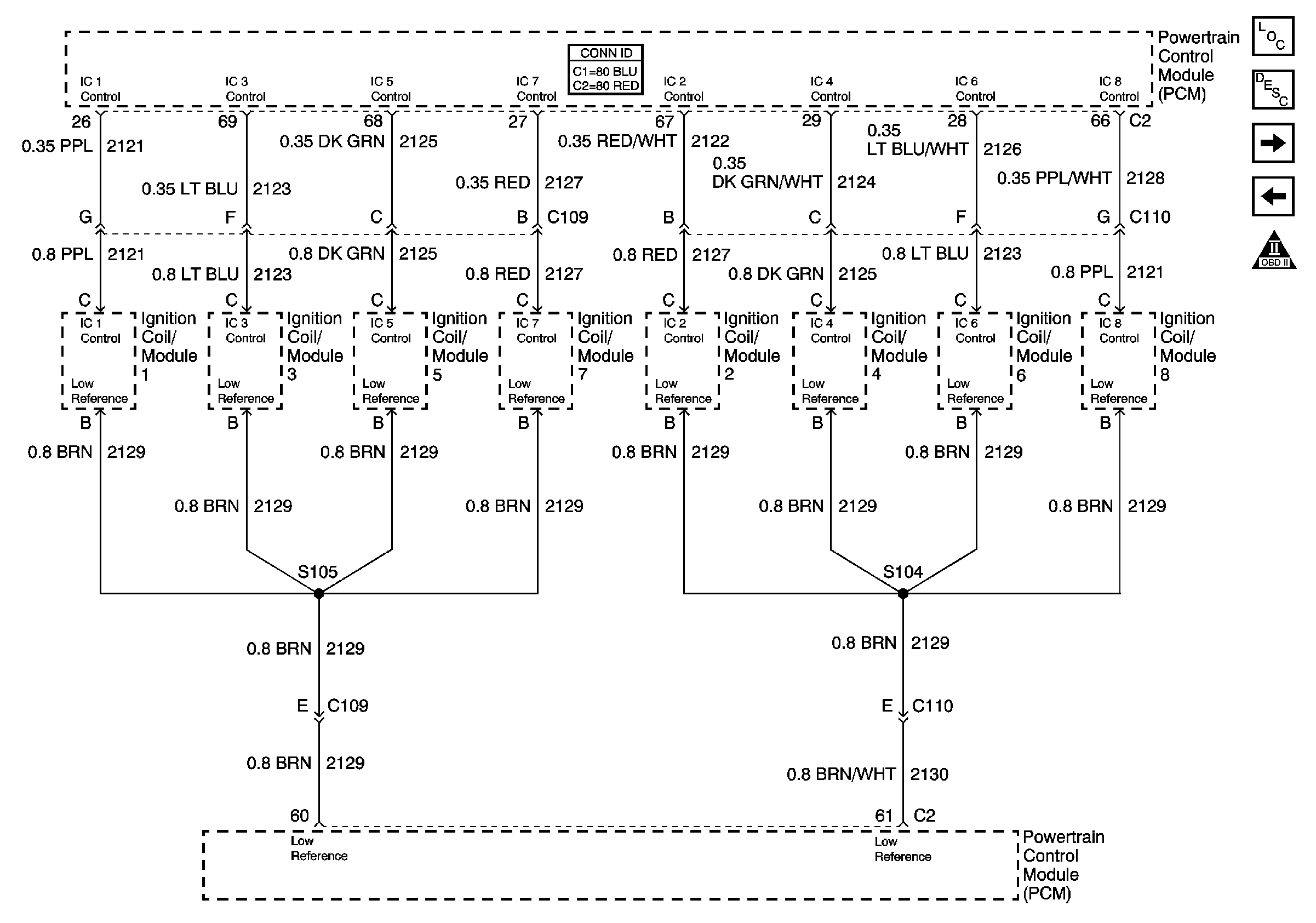
| Figure 6: |
Ignition Control
|
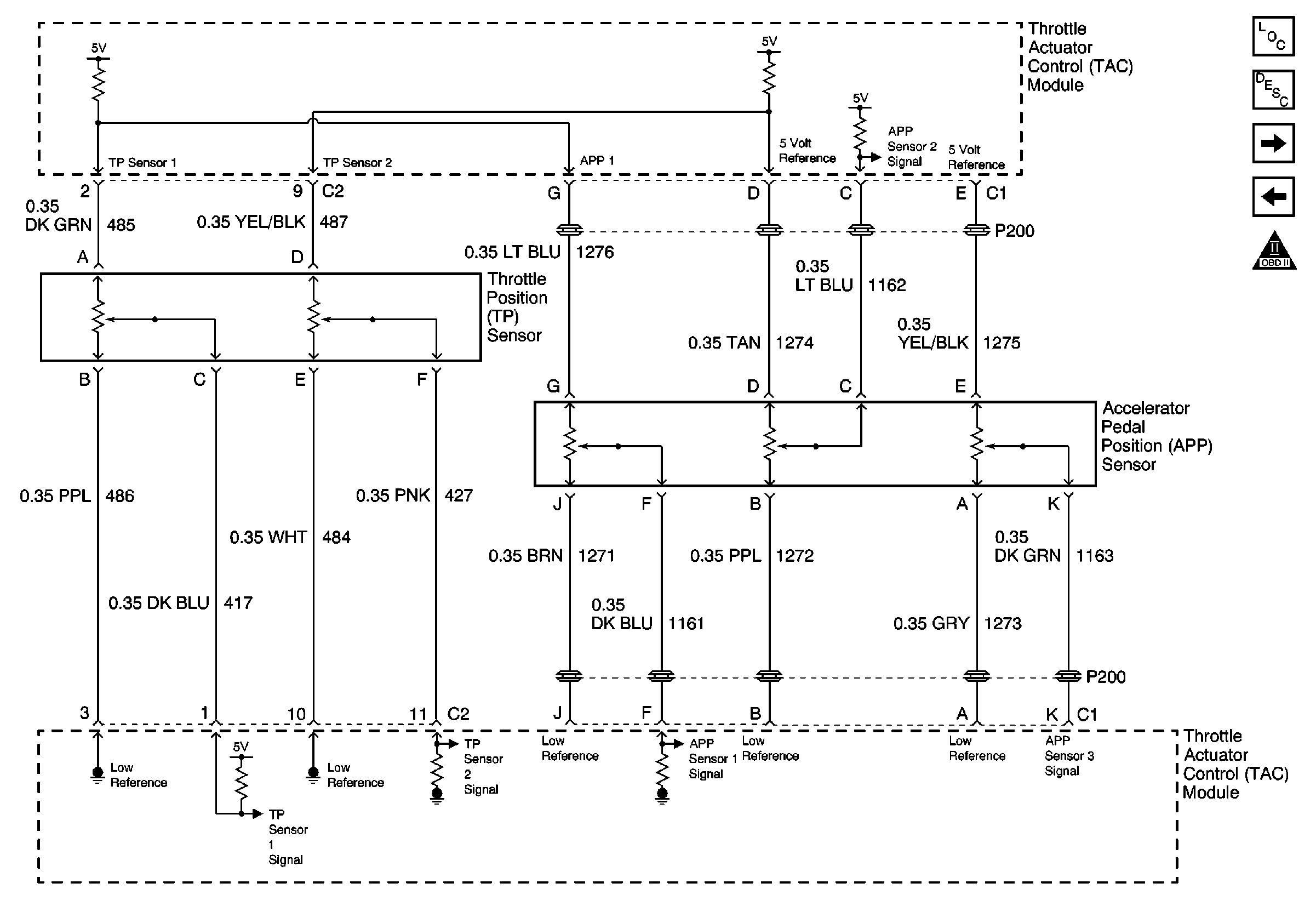
| Figure 7: |
Throttle Position (TP) and Accelerator Pedal Position (APP) Sensors
|
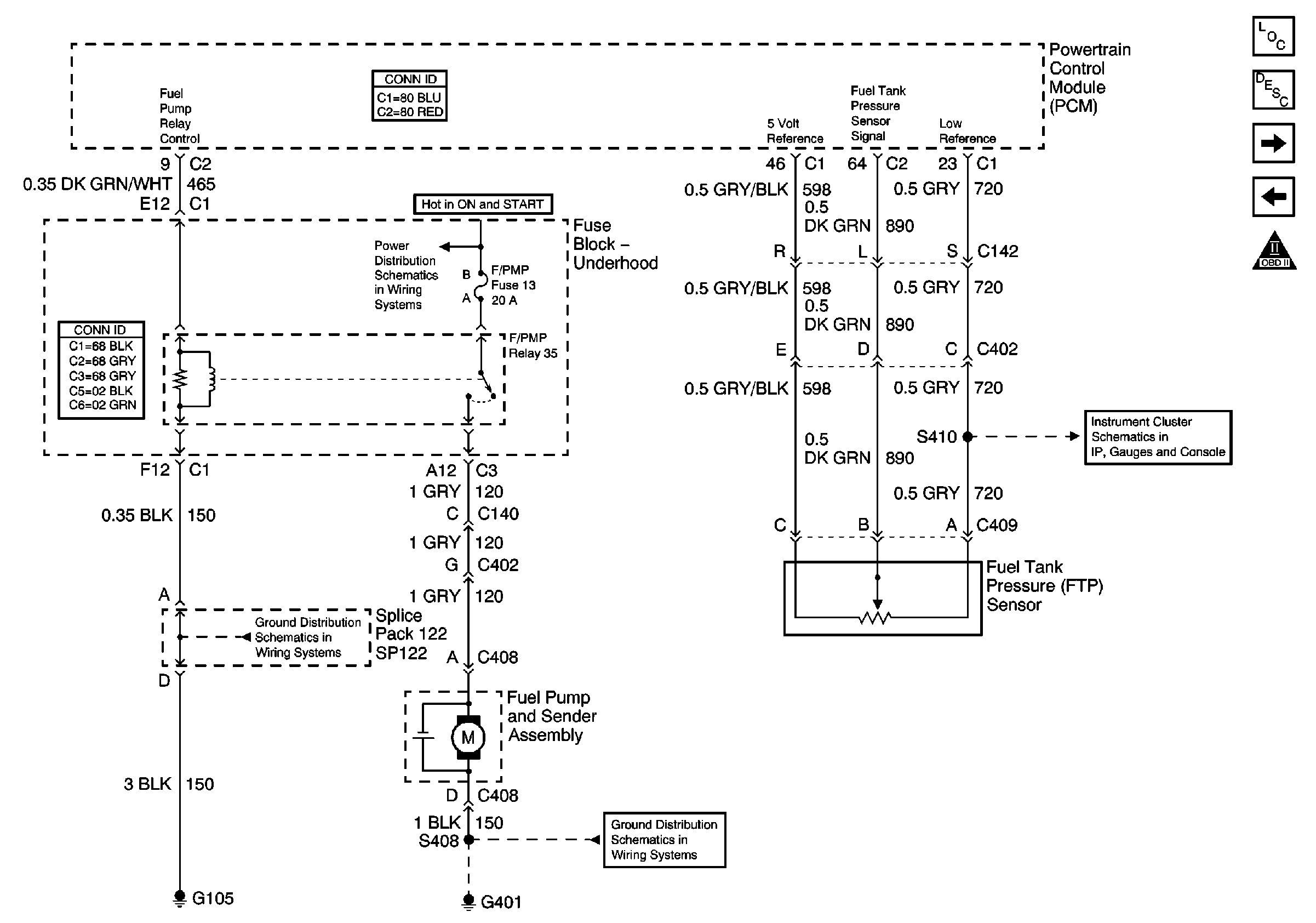
| Figure 8: |
Fuel Pump and Fuel Tank Pressure Sensor
|
| Figure 9: |
AIR System and Evaporative Emission (EVAP) Canister Purge Valve
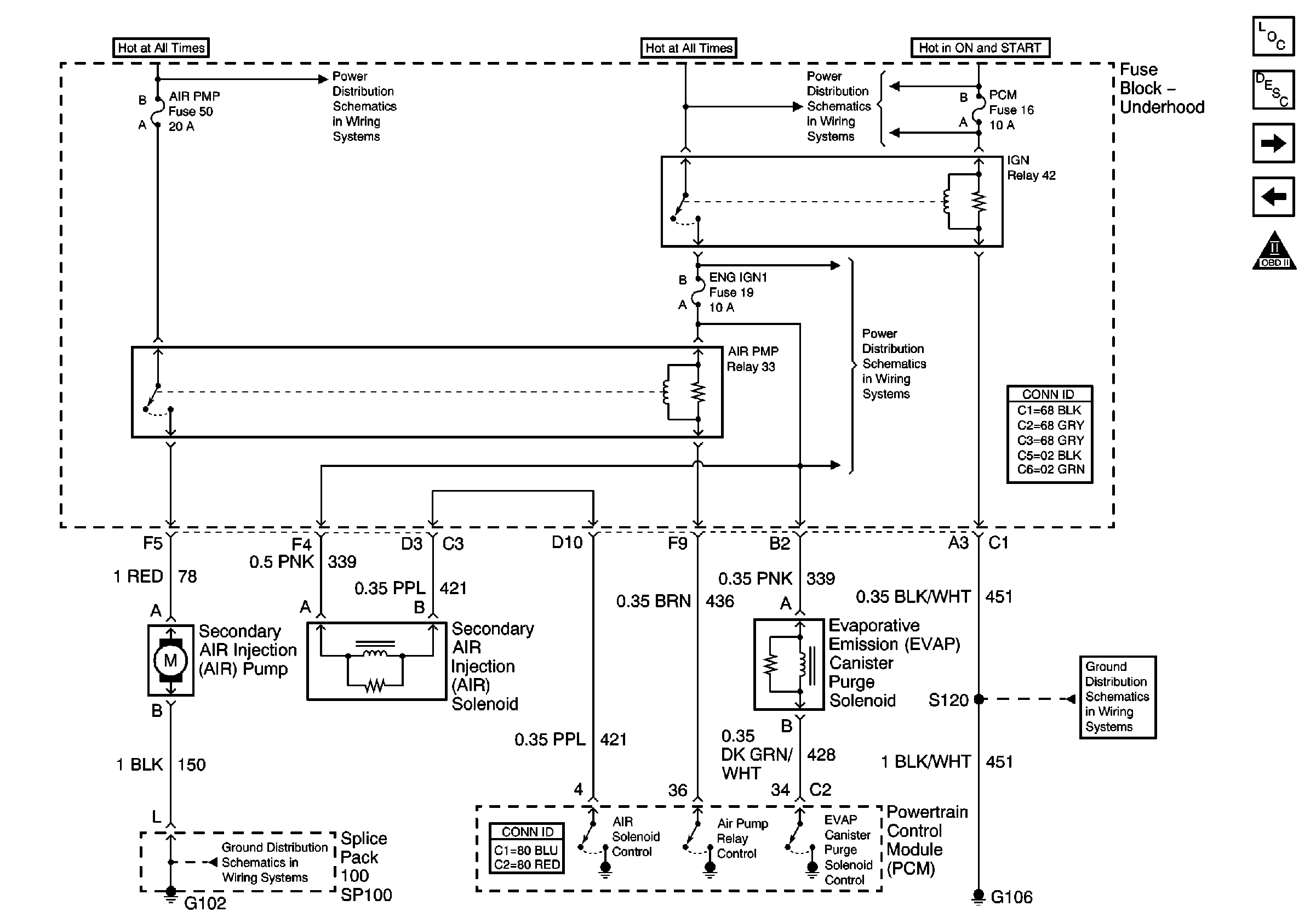
|
| Figure 10: |
Evaporative Emission (EVAP) Vent Valve Solenoid
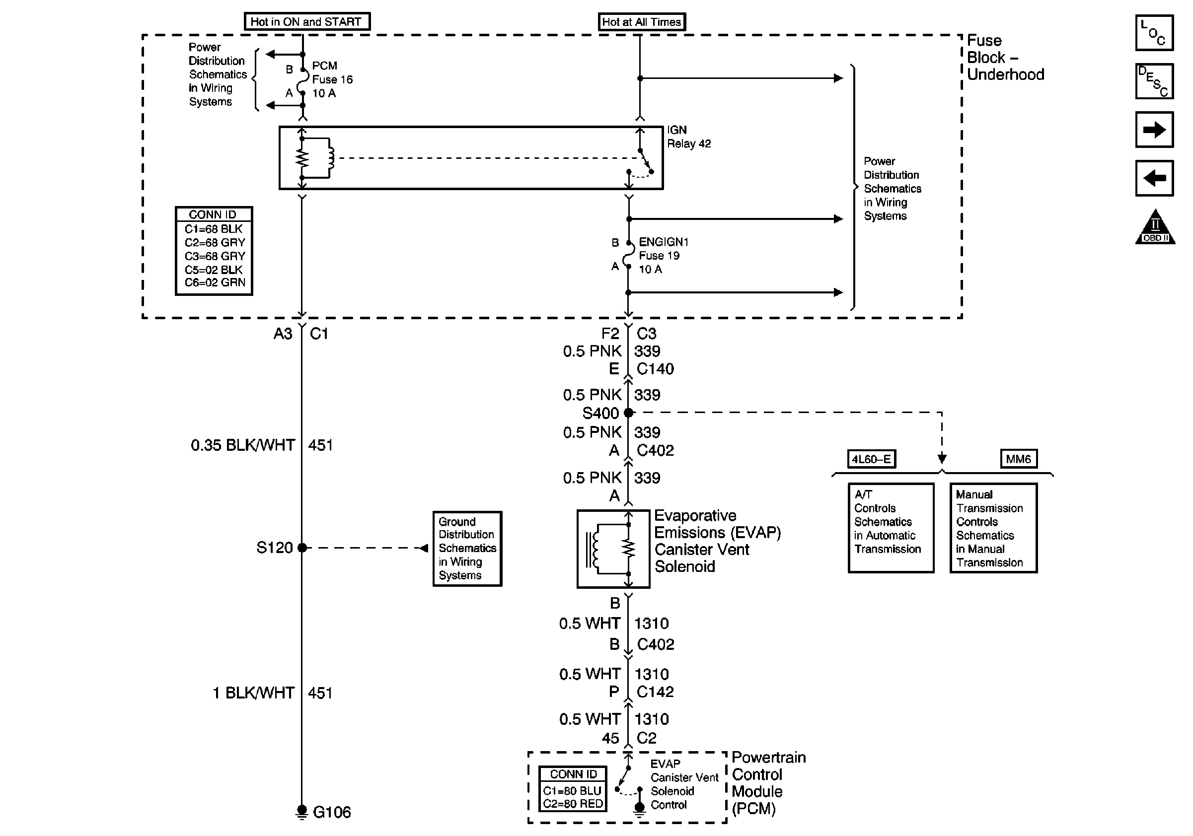
|
| Figure 11: |
Mass Air Flow (MAF) Sensor and Extended Brake Travel Signal
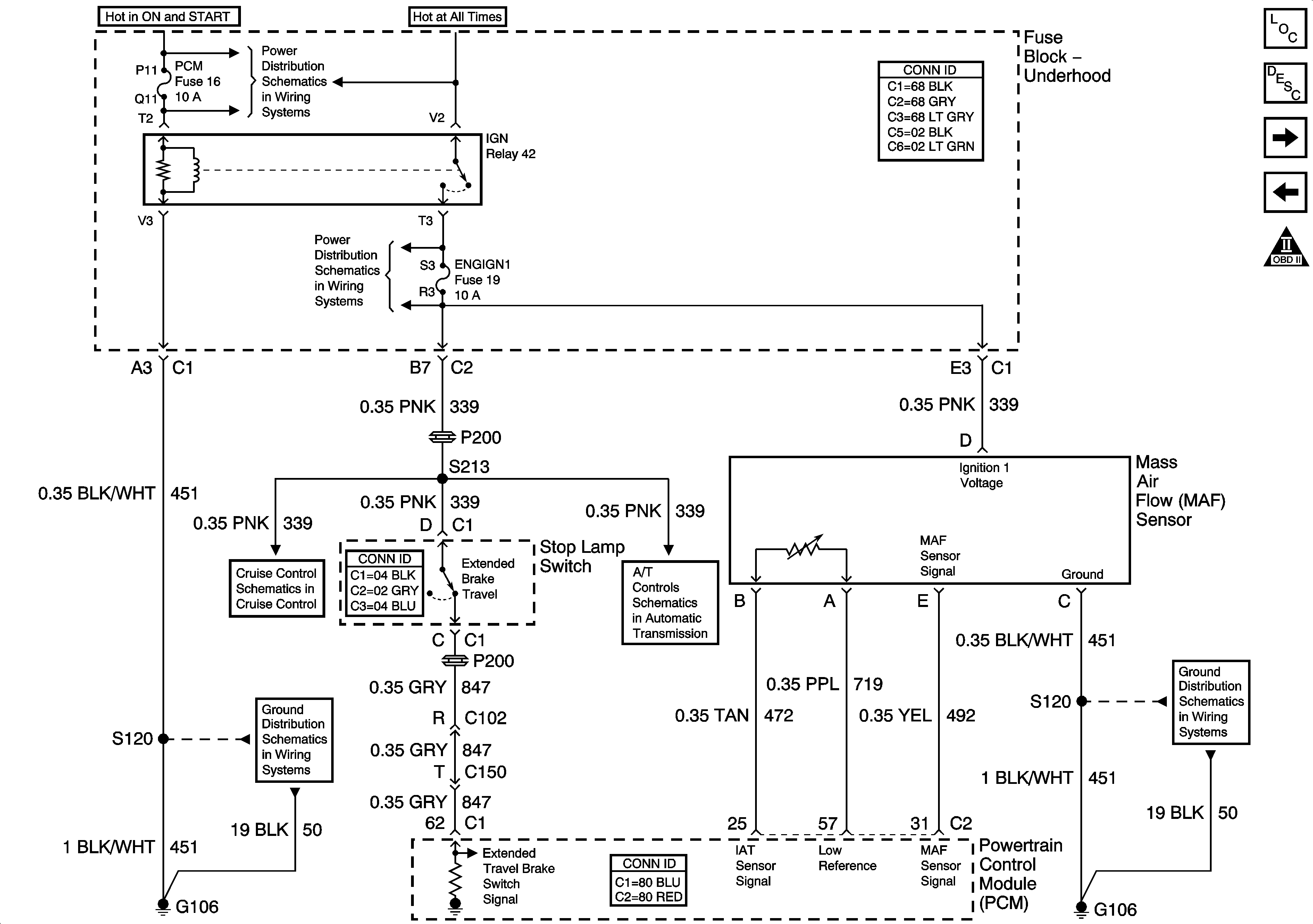
|
| Figure 12: |
Manifold Absolute Pressure (MAP), Engine Coolant Temperature(ECT) and
Vehicle Speed Sensors and Engine Speed Output
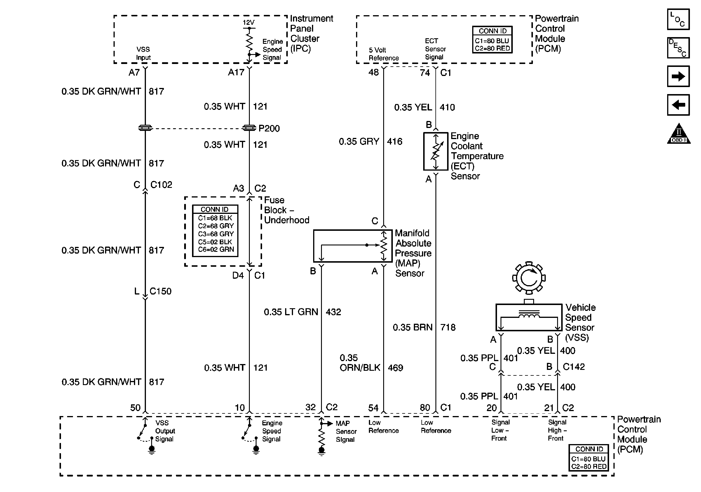
|
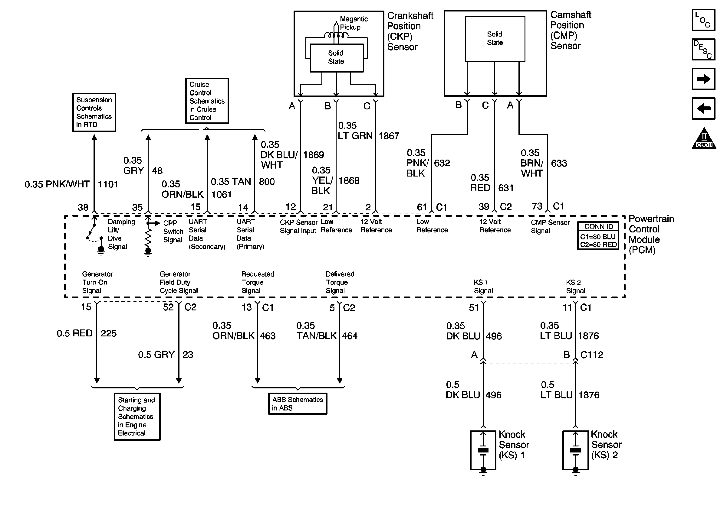
| Figure 13: |
Crankshaft Position (CKP), Camshaft Position (CMP) and Front and Rear
Knock Sensors
|
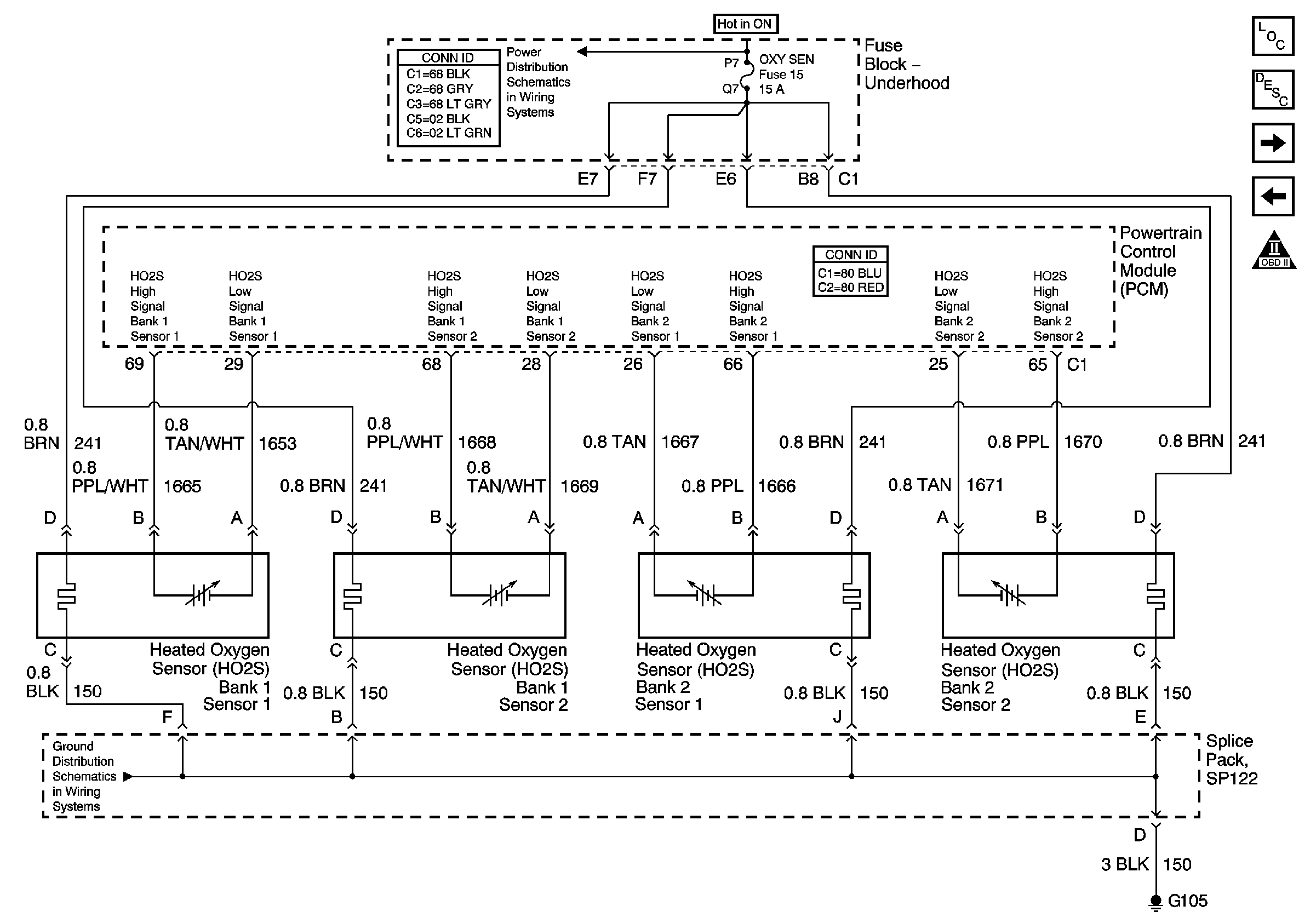
| Figure 14: |
Heated Oxygen Sensors
|
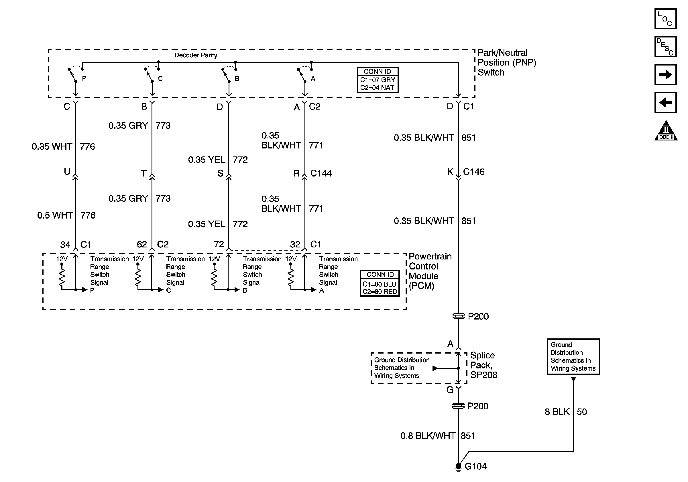
| Figure 15: |
Park Neutral Position and Backup Switch
|
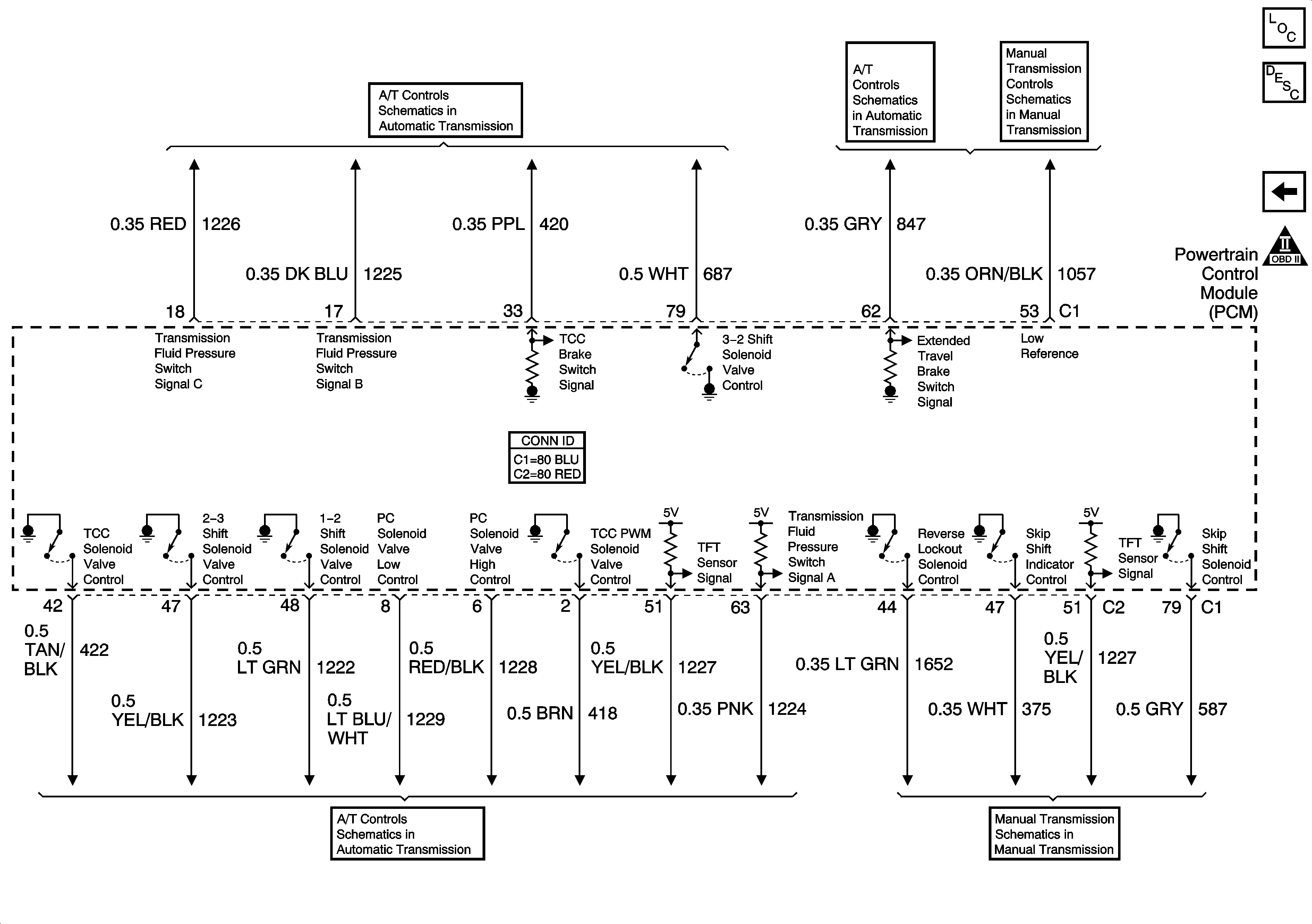
| Figure 16: |
Automatic Transmission
|