Removal Procedure
- Remove the fan shroud. Refer to Fan Shroud Replacement .
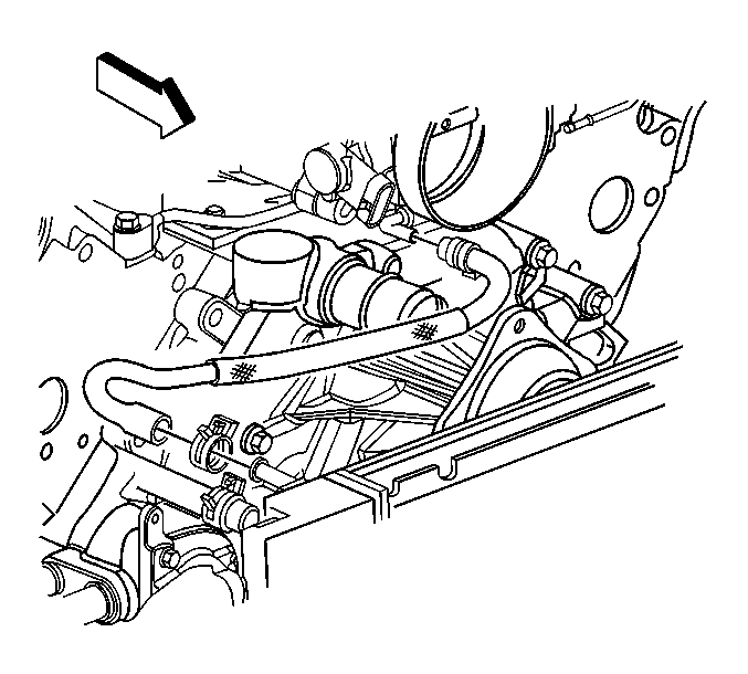
- Reposition the throttle body heater outlet hose clamp at the radiator.
- Remove the throttle body heater outlet hose from the radiator.
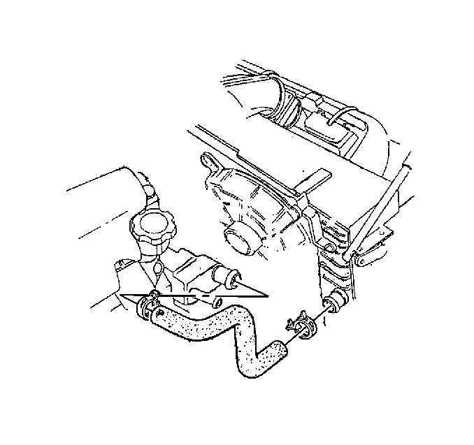
- Reposition the radiator inlet hose clamp at the water pump.
- Remove the radiator inlet hose from the water pump.
- Reposition the radiator outlet hose clamp at the water pump inlet.
- Remove the radiator outlet hose from the water pump inlet.
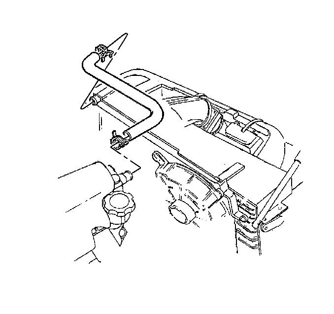
- Reposition the surge tank inlet hose clamp at the radiator.
- Remove the surge tank inlet hose from the radiator.
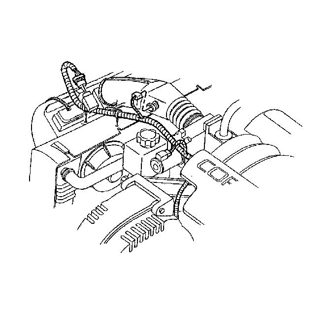
- Remove the connector position assurance (CPA) lock.
- Disconnect the mass air flow (MAF) sensor electrical connector.
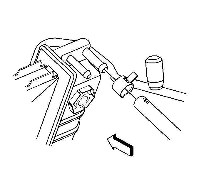
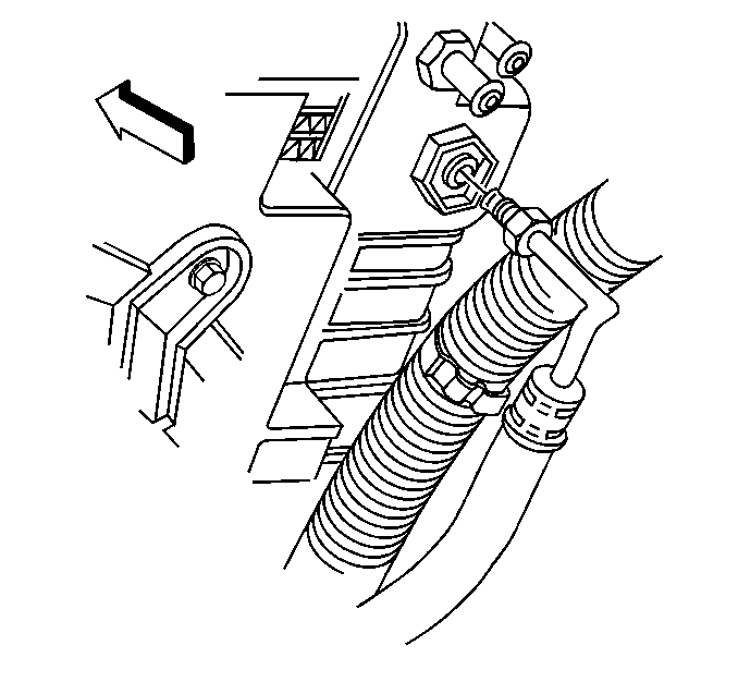
- If equipped, remove the automatic transmission oil cooler lines from the radiator.
- With the aid of an assistant, remove the condenser from the radiator and position it forward.
- Remove the radiator from the vehicle.
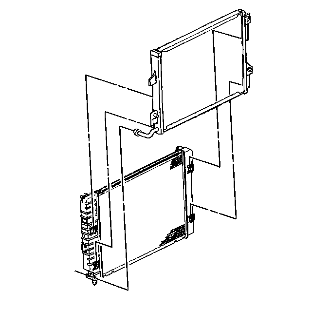
Important : It is not necessary to disconnect the air conditioning (A/C) lines from the condenser.
Installation Procedure
- Install the radiator.
- With the aid of an assistant, install the condenser into the four retaining tabs on the radiator.
- If equipped, install the automatic transmission oil cooler lines to the radiator, if equipped.
- Connect the MAF sensor electrical connector.
- Install the CPA lock.
- Install the surge tank inlet hose to the radiator.
- Position the surge tank inlet hose clamp at the radiator.
- Install the radiator outlet hose to the water pump inlet.
- Position the radiator outlet hose clamp at the water pump inlet.
- Install the radiator inlet hose to the water pump.
- Position the radiator inlet hose clamp at the water pump.
- Install the throttle body heater outlet hose from the radiator.
- Position the throttle body heater outlet hose clamp at the radiator.
- Install the fan shroud. Refer to Fan Shroud Replacement .


Notice: Use the correct fastener in the correct location. Replacement fasteners must be the correct part number for that application. Fasteners requiring replacement or fasteners requiring the use of thread locking compound or sealant are identified in the service procedure. Do not use paints, lubricants, or corrosion inhibitors on fasteners or fastener joint surfaces unless specified. These coatings affect fastener torque and joint clamping force and may damage the fastener. Use the correct tightening sequence and specifications when installing fasteners in order to avoid damage to parts and systems.
Tighten
Tighten the automatic transmission oil cooler lines to 25 N·m
(18 lb ft).


