Left Fuel Tank Pipes Removal Procedure
Tools Required
J 34730-1A Fuel Pressure Gauge
- Disconnect the negative battery cable.
- Relieve the fuel system pressure. Refer to the Fuel Pressure Relief .
- Drain the fuel tanks. Refer to Fuel Tank Draining .
- Remove the left muffler. Refer to Muffler Replacement in Engine Exhaust.
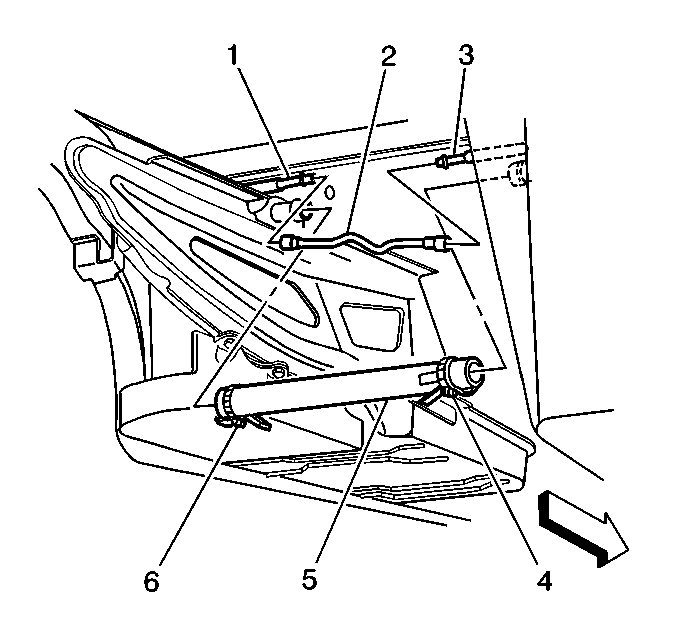
- Disconnect the tank crossover hose (5) at the left fuel tank.
- Disconnect the EVAP pipe (2) at the left tank EVAP pipe (1).
- Cap the EVAP pipe in order to prevent possible contamination.
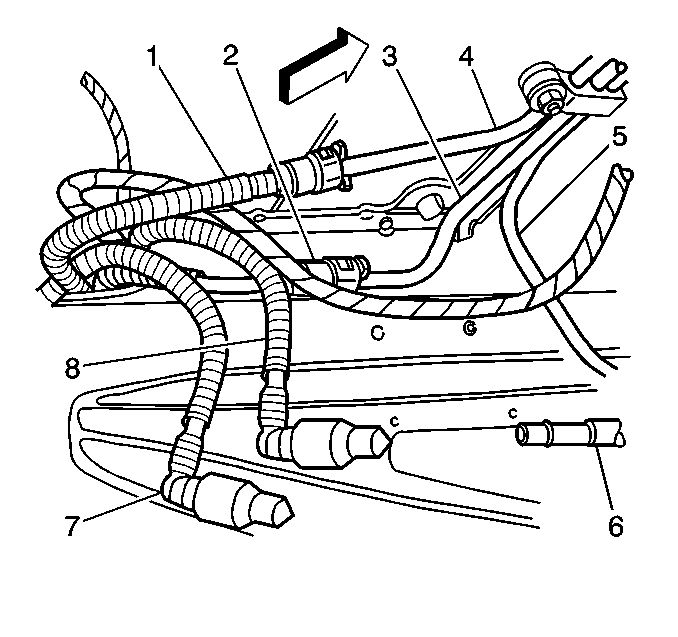
- Disconnect the auxiliary fuel return pipe (1) from the jet pump to the left tank. Refer to Plastic Collar Quick Connect Fitting Service .
- Disconnect the fuel return pipe (7) at the fuel filter/pressure regulator. Refer to Plastic Collar Quick Connect Fitting Service .
- Disconnect the fuel feed pipe (8) at the fuel filter/pressure regulator. Refer to Plastic Collar Quick Connect Fitting Service .
- Disconnect the auxiliary fuel feed rear pipe (2) from the left tank to the jet pump. Refer to Plastic Collar Quick Connect Fitting Service .
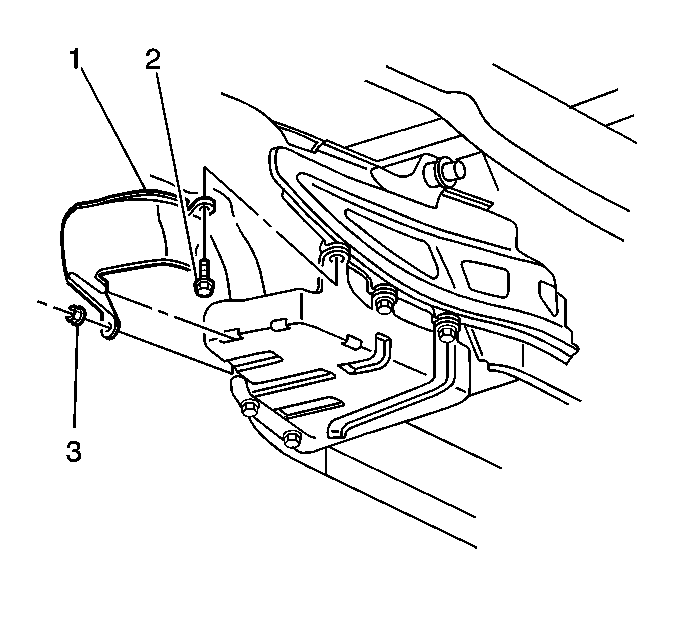
- Remove the left fuel tank shield mount nut (3).
- Remove the left fuel tank shield mount bolt (2).
- Remove the left fuel tank shield (1).
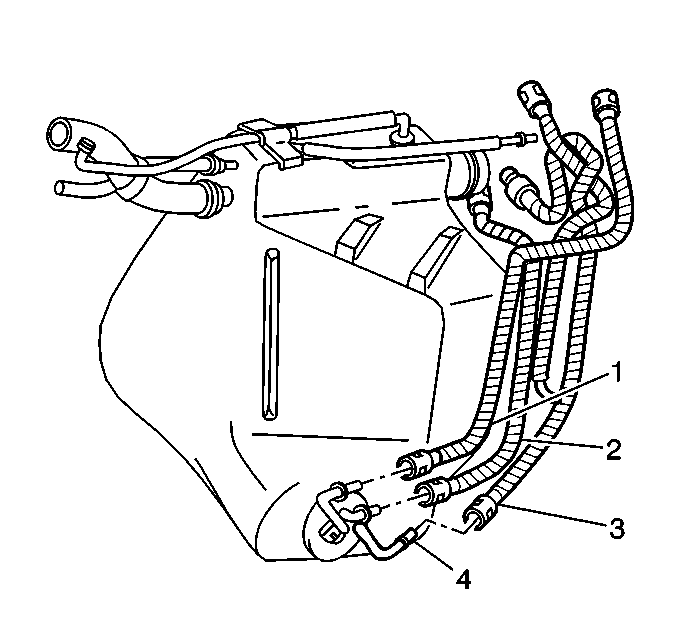
- Disconnect the auxiliary fuel return rear pipe (1) at the fuel sender. Refer to Plastic Collar Quick Connect Fitting Service .
- Disconnect the fuel return rear pipe (2) at the fuel sender. Refer to Plastic Collar Quick Connect Fitting Service .
- Disconnect the fuel feed rear pipe (3) at the fuel sender. Refer to Plastic Collar Quick Connect Fitting Service .
- Remove the left side rear fuel pipes.
- Cap the fuel sender pipes.
- Cap the fuel filter/pressure regulator.
Caution: Unless directed otherwise, the ignition and start switch must be in the OFF or LOCK position, and all electrical loads must be OFF before servicing any electrical component. Disconnect the negative battery cable to prevent an electrical spark should a tool or equipment come in contact with an exposed electrical terminal. Failure to follow these precautions may result in personal injury and/or damage to the vehicle or its components.
Notice: Replace the EVAP pipes and hoses with the original equipment or parts that meet the GM specifications for those parts. The replacement EVAP pipe must have the same type of fittings as the original pipe in order to ensure the integrity of the connection. When replacing EVAP hoses, use only reinforced fuel-resistant hose identified with the word Fluoroelastomer or GM 6163-M on the hose. The inside hose diameter must match the outside pipe diameter. Do not use rubber hose within 100 mm (4 in) of any part of the exhaust system or within 254 mm (10 in) of the catalytic converter.
Notice:
• Do not repair the fuel feed or return pipes. • Replace the fuel feed and return pipes with original equipment
or with parts that meet the GM specifications for those parts. The replacement
pipe must have the same type of fittings as the original pipe in order to
ensure the integrity of the connection.
Important: Mark or identify each fuel pipe in order to aid in installing the pipes in their original positions.
Left Fuel Tank Pipes Installation Procedure
- Remove the caps from the fuel filter/pressure regulator.
- Install and connect the fuel return rear pipe (7) to the fuel filter/pressure regulator. Refer to Plastic Collar Quick Connect Fitting Service .
- Install and connect the auxiliary fuel feed rear pipe (2) from the left tank to jet pump. Refer to Plastic Collar Quick Connect Fitting Service .
- Install and connect the fuel feed pipe (8) at the fuel filter/pressure regulator. Refer to Plastic Collar Quick Connect Fitting Service .
- Install and connect the auxiliary fuel return rear pipe (1) from the jet pump to left tank. Refer to Plastic Collar Quick Connect Fitting Service .
- Remove the caps from the fuel sender pipes.
- Connect the fuel feed rear pipe (3) at the fuel sender. Refer to Plastic Collar Quick Connect Fitting Service .
- Connect the fuel return rear pipe (2) at the fuel sender. Refer to Plastic Collar Quick Connect Fitting Service .
- Connect the auxiliary fuel return rear pipe (1) at the fuel sender. Refer to Plastic Collar Quick Connect Fitting Service .
- Install the left fuel tank shield (1).
- Install the left fuel tank shield mount bolt (2).
- Install the left fuel tank shield mount nut (3).
- Remove the cap from the EVAP pipe.
- Connect the EVAP pipe (2) at the left tank EVAP pipe (1).
- Connect the tank crossover hose (5) at the left fuel tank.
- Push the clamp (6) outboard against the fuel tank keeping the clamp parallel with the white stripe on the tank crossover hose.
- Install the left muffler. Refer to Muffler Replacement in Engine Exhaust.
- Refill the fuel system.
- Tighten the fuel filler cap.
- Connect the negative battery cable.
- Inspect for leaks.
- Program the transmitters. Refer to Transmitter Programming/Synchronization in Keyless Entry.
- Perform the idle learn procedure. Refer to Idle Learn .

Important: Lubricate the fuel pipes in order to aid in installation. Use mechanic's wire attached to the fuel sender end of the fuel pipe in order to pull the fuel pipe through the tunnel reinforcement opening. Pull the fuel pipe through from the top down.


Tighten
| • | Tighten the fuel tank shield mount bolt to 25 N·m (18 lb ft). |
| • | Tighten the fuel tank shield mount nut to 12 N·m (106 lb in). |

Tighten
Tighten the tank crossover hose clamp to 4 N·m (35 lb in).
| 21.1. | Turn the ignition switch ON for 2 seconds. |
| 21.2. | Turn the ignition switch OFF for 10 seconds. |
| 21.3. | Turn the ignition switch ON. |
| 21.4. | Inspect for fuel leaks. |
Right Fuel Tank Pipes Removal Procedure
Tool Required
J 34730-1A Fuel Pressure Gauge
Notice:
• Do not repair the fuel feed or return pipes. • Replace the fuel feed and return pipes with original equipment
or with parts that meet the GM specifications for those parts. The replacement
pipe must have the same type of fittings as the original pipe in order to
ensure the integrity of the connection.
Important: Mark or identify each fuel pipe in order to aid in installing the pipes in their original positions.
- Disconnect the negative battery cable.
- Relieve the fuel system pressure. Refer to the Fuel Pressure Relief .
- Drain the fuel tanks. Refer to Fuel Tank Draining .
- Remove the left and right muffler. Refer to Muffler Replacement in Engine Exhaust.
- Disconnect the tank crossover hose (5) at the right fuel tank and the left fuel tank.
- Disconnect the EVAP pipe (2) at the right tank EVAP pipe (3) and the left tank EVAP pipe (1).
- Cap the open pipes in order to prevent possible contamination.
- Disconnect the auxiliary fuel return rear pipe (1) from the jet pump to the left tank. Refer to Plastic Collar Quick Connect Fitting Service .
- Disconnect the auxiliary fuel feed rear pipe (2) from the left tank to the jet pump. Refer to Plastic Collar Quick Connect Fitting Service .
- Remove the right fuel tank shield mount nut (3).
- Remove the right fuel tank shield mount bolt (2).
- Remove the right fuel tank shield (1).
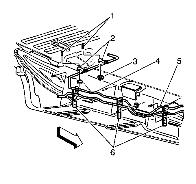
- Remove the fuel pipes from the two rear upper fuel and EVAP pipe retainers (2).
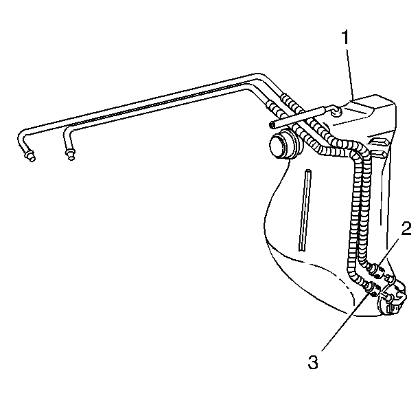
- Disconnect the auxiliary fuel return rear pipe (3) from the jet pump to the left tank. Refer to Plastic Collar Quick Connect Fitting Service .
- Disconnect the auxiliary fuel feed rear pipe (2) from the left tank to the jet pump. Refer to Plastic Collar Quick Connect Fitting Service .
- Remove the auxiliary fuel return rear pipe from the jet pump to the left tank.
- Remove the auxiliary fuel feed rear pipe from the left tank to the jet pump.
- Cap the fuel sender pipes and the left tank fuel pipes.

Caution: Unless directed otherwise, the ignition and start switch must be in the OFF or LOCK position, and all electrical loads must be OFF before servicing any electrical component. Disconnect the negative battery cable to prevent an electrical spark should a tool or equipment come in contact with an exposed electrical terminal. Failure to follow these precautions may result in personal injury and/or damage to the vehicle or its components.


Right Fuel Tank Pipes Installation Procedure
- Install the auxiliary fuel feed rear pipe (2) from the left tank to the jet pump.
- Install the auxiliary fuel return rear pipe (3) from the jet pump to the left tank.
- Remove the caps from the pipes.
- Connect the auxiliary fuel return rear pipe (3) from the jet pump to the left tank. Refer to Plastic Collar Quick Connect Fitting Service .
- Connect the auxiliary fuel feed rear pipe (2) from the left tank to the jet pump. Refer to Plastic Collar Quick Connect Fitting Service .
- Install the fuel pipes into the two rear upper fuel and EVAP pipe retainers (2).
- Connect the auxiliary fuel feed rear pipe (2) from the left tank to the jet pump. Refer to Plastic Collar Quick Connect Fitting Service .
- Connect the auxiliary fuel return rear pipe (1) from the jet pump to the left tank. Refer to Plastic Collar Quick Connect Fitting Service .
- Install the right fuel tank shield (1).
- Install the right fuel tank shield mount bolt (2).
- Install the right fuel tank shield mount nut (3).
- Remove the caps from the pipes.
- Connect the EVAP pipe (2) at the right tank EVAP pipe (3) and the left tank EVAP pipe (1).
- Connect the tank crossover hose (5) at the right fuel tank and the left fuel tank.
- Push the clamp (4) outboard against the fuel tank keeping the clamp parallel with the white stripe on the tank crossover hose.
- Install the right and left muffler. Refer to Muffler Replacement in Engine Exhaust.
- Refill the fuel system.
- Tighten the fuel filler cap.
- Connect the negative battery cable.
- Inspect for leaks.
- Program the transmitters. Refer to Transmitter Programming/Synchronization in Keyless Entry.
- Perform the idle learn procedure. Refer to Idle Learn .

Important: Lubricate the fuel pipes in order to aid in installation. Use mechanic's wire attached to the fuel sender end of the fuel pipe in order to pull the fuel pipe through the tunnel reinforcement opening. Pull the fuel pipe through from the top down.

Notice: Use the correct fastener in the correct location. Replacement fasteners must be the correct part number for that application. Fasteners requiring replacement or fasteners requiring the use of thread locking compound or sealant are identified in the service procedure. Do not use paints, lubricants, or corrosion inhibitors on fasteners or fastener joint surfaces unless specified. These coatings affect fastener torque and joint clamping force and may damage the fastener. Use the correct tightening sequence and specifications when installing fasteners in order to avoid damage to parts and systems.
Tighten
Tighten the fuel and EVAP pipe retainer nuts to 3 N·m (27 lb in).


Tighten
| • | Tighten the fuel tank shield mount bolt to 25 N·m (18 lb ft). |
| • | Tighten the fuel tank shield mount nut to 12 N·m (106 lb in). |

Tighten
Tighten the tank crossover hose clamps to 4 N·m (35 lb in).
| 20.1. | Turn the ignition switch ON for 2 seconds. |
| 20.2. | Turn the ignition switch OFF for 10 seconds. |
| 20.3. | Turn the ignition switch ON. |
| 20.4. | Inspect for fuel leaks. |
