Removal Procedure
Tools Required
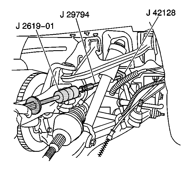
| • | J 2619-O1 Slide Hammer |
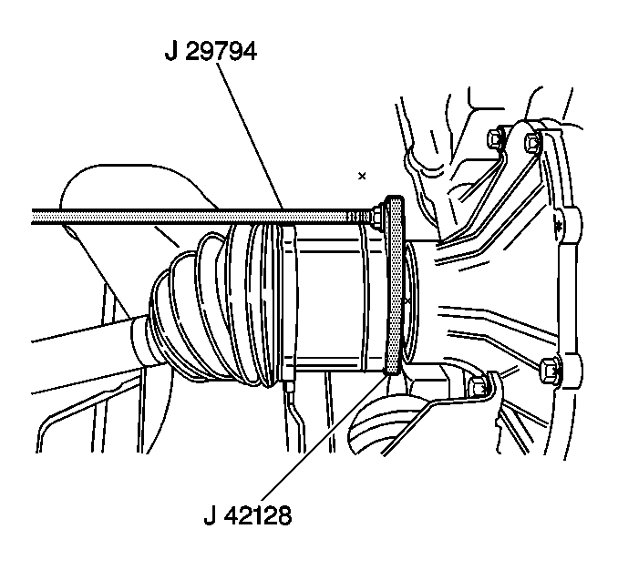
| • | J 29794 Extension |
| • | J 42128 Axle Shaft Remover |
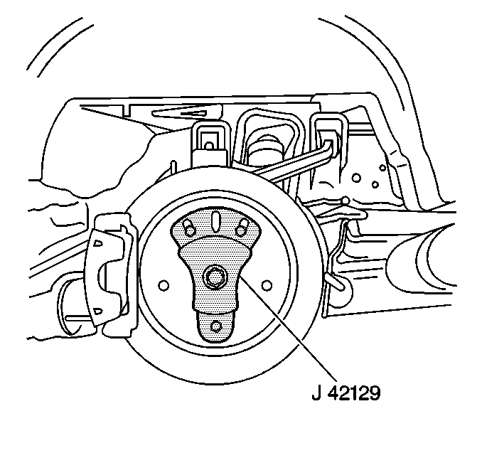
| • | J 42129 Rear Hub Spindle Remover |
- Shift the transmission into PARK (A/T) or NEUTRAL (M/T).
- Apply the parking brake.
- Raise and suitably support the vehicle. Refer to Lifting and Jacking the Vehicle in General Information.
- Remove the tire and wheel assembly. Refer to Tire and Wheel Removal and Installation in Tires and Wheels.
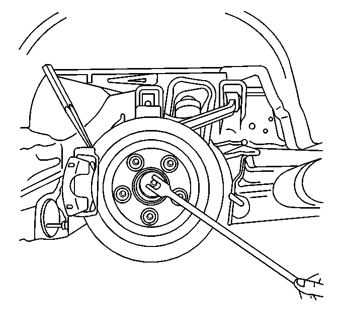
- Insert a drift or punch into the brake rotor cooling fins and against the brake caliper to prevent the wheel hub and bearing from turning.
- Remove the spindle nut retaining the rear wheel drive shaft to the hub.
- Remove the drift or punch.
- Release the parking brake.
- Remove the rear transverse spring. Refer to Rear Transverse Spring Replacement in Rear Suspension.
- Separate the outer tie rod end from the knuckle and reposition the tie rod toward the rear of the vehicle. Refer to Tie Rod Replacement in Rear Suspension.
- Disconnect the wheel speed sensor electrical connector.
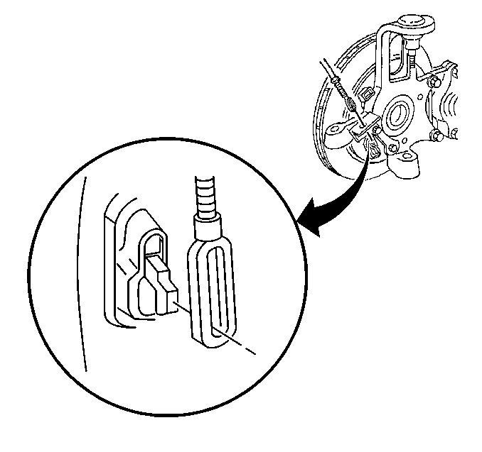
- Disconnect the parking brake cable from the parking brake lever.
- Remove the parking brake cable from the bracket and reposition toward the rear.
- Install J 42129 onto the wheel hub and secure with wheel nuts.
- Begin to disengage the drive shaft from the wheel hub and bearing.
- Separate the lower ball joint from the suspension knuckle. Refer to Knuckle Replacement in Rear Suspension.
- Disengage the drive shaft completely from the wheel hub and bearing.
- Support the drive shaft.
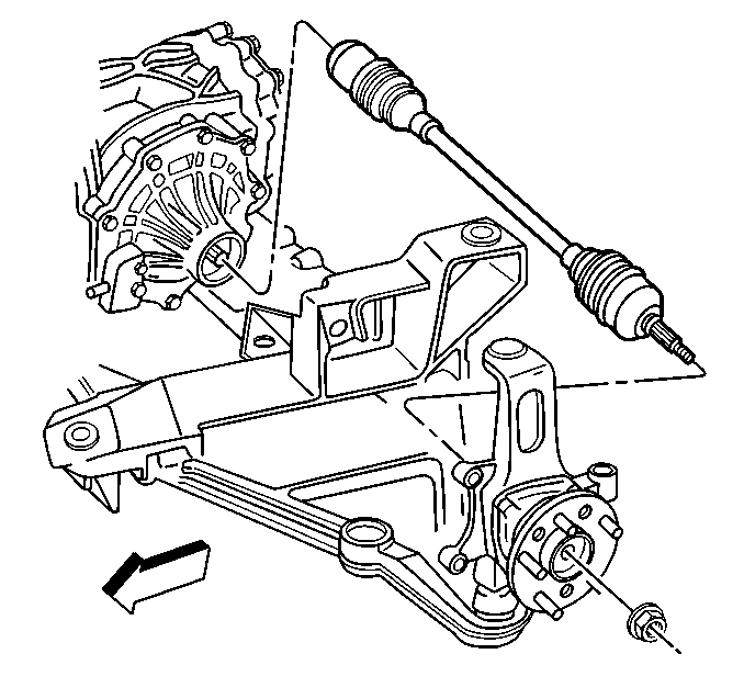
- Support the suspension knuckle and upper control arm and reposition the knuckle toward the front of the vehicle.
- Assemble the J 42128 , J 29794 , and J 2619-O1 .
- Install the J 42128 evenly onto the rear beveled surface of the drive shaft inner joint housing.
- Disengage the drive shaft from the rear axle differential using the J 42128 , J 29794 , and J 2619-O1 , then remove the tool assembly.
- Remove the drive shaft from the vehicle.
- Remove J 42129 from the wheel hub.
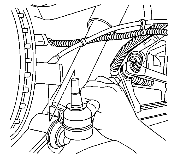
Important: Do not loosen the outer tie rod jam nut.
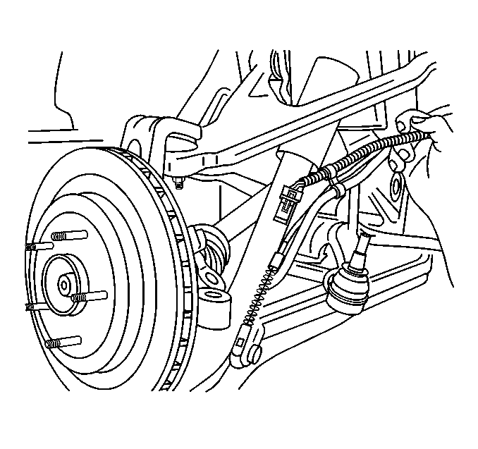
This will provide additional clearance to the lower ball joint nut.
Important: Be sure to support the drive shaft until it is removed.
Installation Procedure
- Position the drive shaft to the rear axle differential output shaft.
- Carefully align and guide the drive shaft onto the differential output shaft.
- Engage the drive shaft fully onto the differential output shaft using light force.
- Check to be certain that the drive shaft is fully seated on the differential output shaft.
- Begin to position the suspension knuckle to the drive shaft.
- Align and carefully guide the drive shaft into the wheel hub and bearing but do not seat fully.
- Connect the lower ball joint to the suspension knuckle. Refer to Knuckle Replacement in Rear Suspension.
- Install the parking brake cable into the bracket.
- Connect the parking brake cable to the parking brake lever.
- Connect the wheel speed sensor electrical connector.
- Connect the outer tie rod end to the suspension knuckle. Refer to Tie Rod Replacement in Rear Suspension.
- Install the rear transverse spring. Refer to Rear Transverse Spring Replacement in Rear Suspension.
- Set the parking brake.
- Insert a drift or punch into the brake rotor cooling fins and against the caliper to prevent the wheel hub and bearing from turning.
- Begin to install the drive shaft retaining nut onto the drive shaft by hand.
- Slowly tighten the nut to draw the drive shaft to the wheel hub and bearing.
- Remove the drift or punch.
- Release the parking brake.
- Install the tire and wheel assembly. Refer to Tire and Wheel Removal and Installation in Tires and Wheels.
- Lower the vehicle.

Important: Be sure to support the drive shaft until it is completely installed.
Important: Use care not to damage the rear axle differential output shaft seal.
This will provide additional clearance to the lower ball joint nut.


Notice: Use the correct fastener in the correct location. Replacement fasteners must be the correct part number for that application. Fasteners requiring replacement or fasteners requiring the use of thread locking compound or sealant are identified in the service procedure. Do not use paints, lubricants, or corrosion inhibitors on fasteners or fastener joint surfaces unless specified. These coatings affect fastener torque and joint clamping force and may damage the fastener. Use the correct tightening sequence and specifications when installing fasteners in order to avoid damage to parts and systems.
Tighten
Tighten the drive axle spindle nut to 160 N·m (118 lb ft).
