Removal Procedure
Tools required
J 42188 Ball Joint Separator
- Raise and support the vehicle. Refer to Lifting and Jacking the Vehicle in General Information.
- Remove the tire and wheel assembly. Refer to Tire and Wheel Removal and Installation in Tires and Wheels.
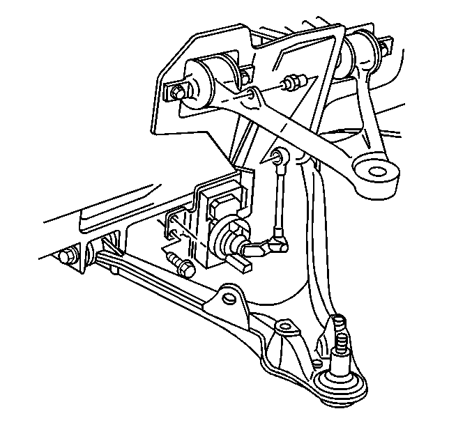
- Disconnect the real time damping (RTD) sensor link.
- Support the lower control arm with a jackstand.
- Loosen the ball joint stud nut but do not remove the nut.
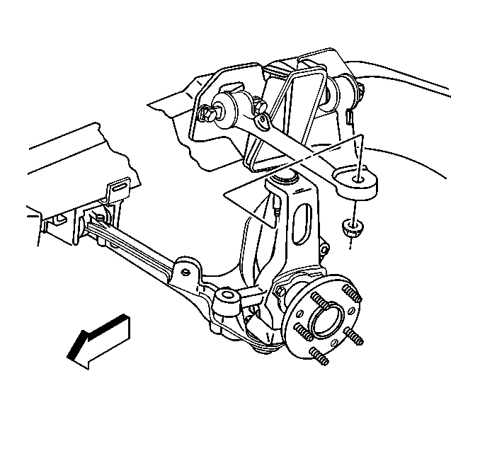
- Using tool J 42188 separate the upper ball joint stud from the upper control arm.
- Remove tool J 42188 from the ball joint stud.
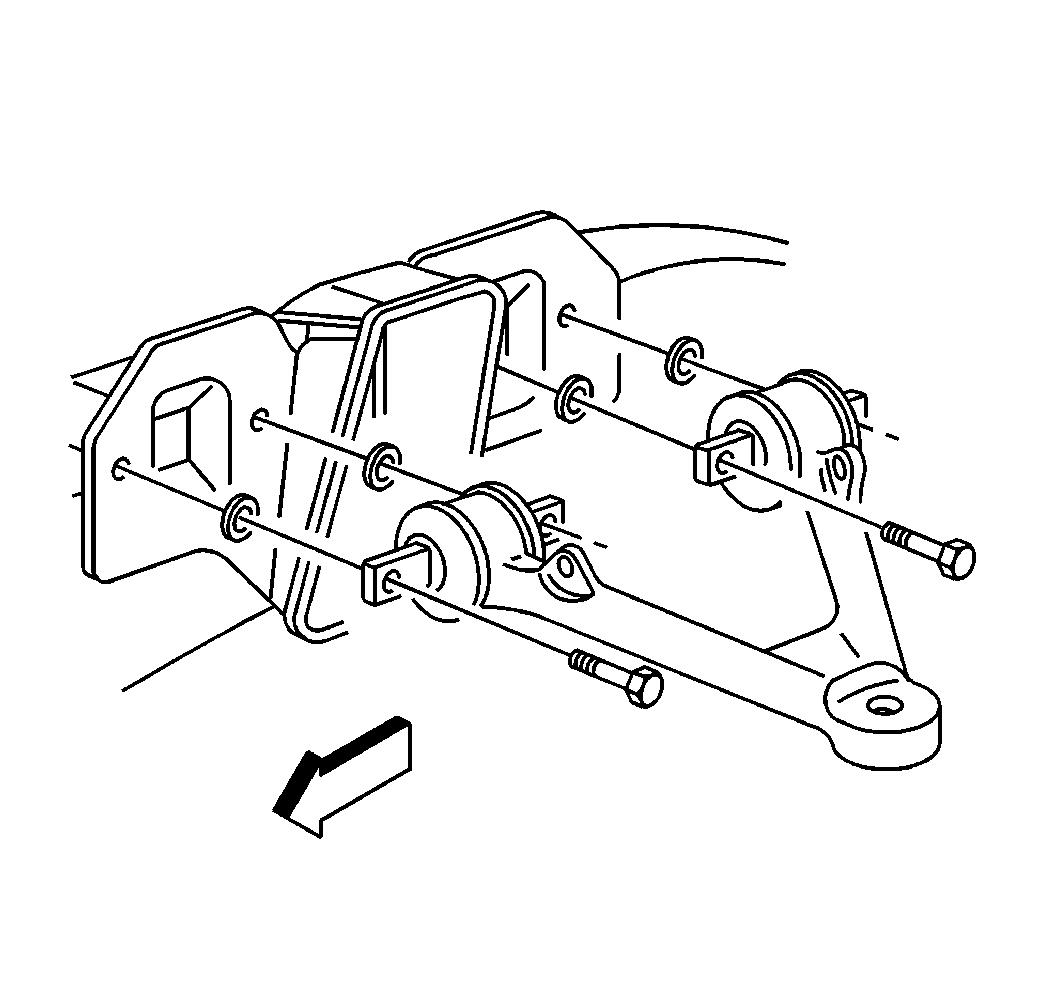
- Remove the upper control arm bolts and shims. Note the number and position of the shims for installation purposes.
- Remove the upper control arm from the vehicle.


Remove the ball joint stud nut from the ball joint stud.

Important: The upper control arm shims will have an effect on the camber and the caster. Make sure to use an equal thickness of shims on both sides of each individual upper control arm bushing.
Installation Procedure
- Install the upper control arm to the vehicle.
- Install the upper control arm shims.
- Install the upper control arm mounting bolts to the upper control arm and frame rail.
- Install the upper ball joint stud into the upper control arm. It will be necessary to use an allen wrench to keep the ball joint stud from spinning while tightening the ball joint stud nut.
- Tighten the upper control arm ball joint stud nut to 20 N·m (15 lb ft) to seat the ball joint stud.
- Turn the ball joint nut an additional 250 degrees.
- Check the ball joint nut for a minimum final torque of 55 N·m (41 lb ft).
- Connect the real time damping (RTD) sensor link.
- Remove the jackstand.
- Install the tire and wheel assembly. Refer to Tire and Wheel Removal and Installation in Tires and Wheels.
- Lower the vehicle.

Important: The upper control arm shims will have an effect on the camber and the caster. Make sure to use an equal thickness of shims on both sides of each individual upper control arm bushing.
Notice: Use the correct fastener in the correct location. Replacement fasteners must be the correct part number for that application. Fasteners requiring replacement or fasteners requiring the use of thread locking compound or sealant are identified in the service procedure. Do not use paints, lubricants, or corrosion inhibitors on fasteners or fastener joint surfaces unless specified. These coatings affect fastener torque and joint clamping force and may damage the fastener. Use the correct tightening sequence and specifications when installing fasteners in order to avoid damage to parts and systems.
Tighten
Tighten the upper control arm mounting bolts to 65 N·m
(48 lb ft).

Tighten

