For 1990-2009 cars only
Steering Shaft, Lower Bearing, and Jacket - Disassemble - Off Vehicle With Sensor Non-Telescoping Column
Tools Required
J 21854-01 Pivot Pin Remover
- Remove the electronic column lock module. Refer to Electronic Column Lock Module - Disassemble - Off Vehicle .
- Remove the tilt spring. Refer to Tilt Spring - Disassemble - Off Vehicle .
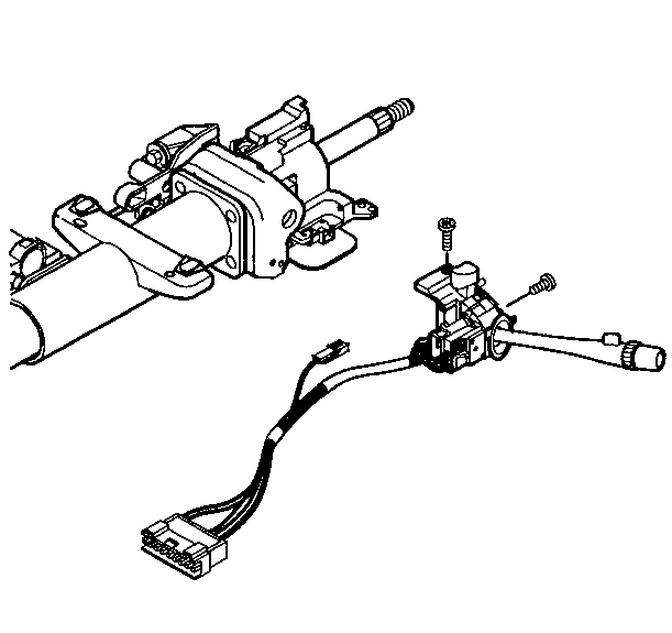
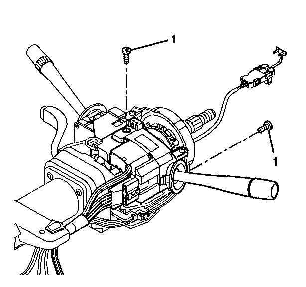
- Remove the 2 pan head tapping screws from the turn signal and multifunction switch assembly.
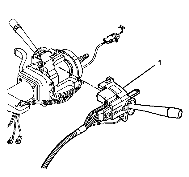
- Remove the turn signal and multifunction switch assembly.
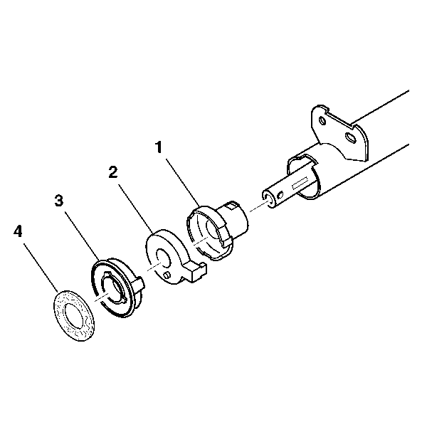
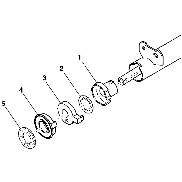
- Remove the steering shaft seal (4).
- Remove the sensor retainer (3).
- Remove the high resolution steering wheel position sensor assembly (2).
- Remove the adapter and bearing assembly (1).
- Remove the 2 pivot pins (1) from the steering column support assembly using J 21854-01 .
- Install the tilt lever.
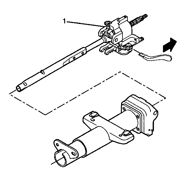
- Pull the tilt lever to disengage the steering column lock shoes from the dowel pins in the steering column tilt head assembly.
- Remove the steering column tilt head assembly (1) with the steering shaft assembly from the steering column jacket assembly.
- Remove the steering shaft assembly (2) from the steering column tilt head assembly (1).
- Mark the race and upper shaft assembly.
- Mark the lower steering shaft assembly.
- Tilt the race and upper shaft assembly 90 degrees to the lower steering shaft assembly to disengage.
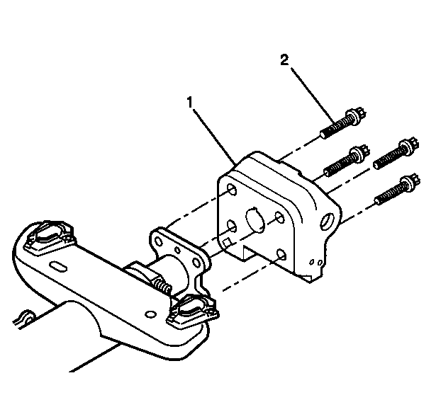
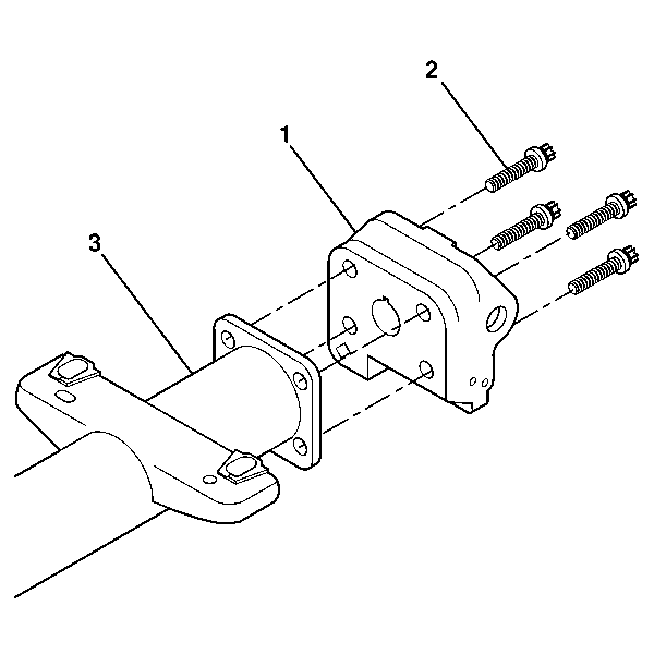
- Remove the 4 TORX® head screws (2).
- Remove the steering column support assembly (1) from the steering column jacket assembly (3).

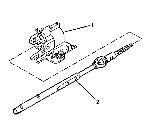

Important: Carefully mark the parts to ensure proper assembly. Failure to assemble properly will cause the steering wheel to be turned 180 degrees.
Steering Shaft, Lower Bearing, and Jacket - Disassemble - Off Vehicle Without Sensor Non-Telescoping Column
Tools Required
J 21854-01 Pivot Pin Remover
- Remove the electronic column lock module. Refer to Electronic Column Lock Module - Disassemble - Off Vehicle .
- Remove the tilt spring. Refer to Tilt Spring - Disassemble - Off Vehicle .
- Remove the 2 pan head tapping screws from the turn signal and multifunction switch assembly.
- Remove the turn signal and multifunction switch assembly.
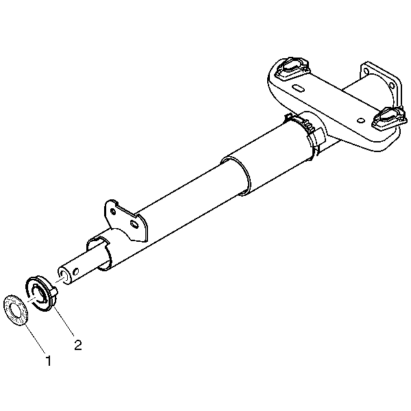
- Remove the steering shaft seal (1).
- Remove the sensor retainer (2).
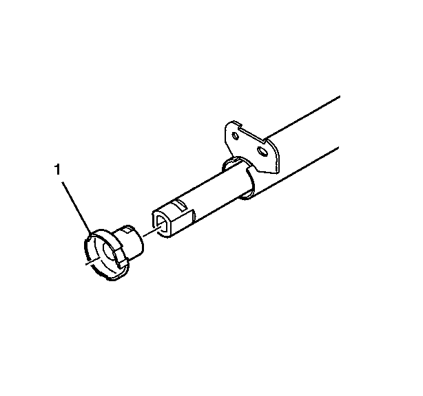
- Remove the adapter and bearing assembly (1).
- Remove the 2 pivot pins (1) from the steering column support assembly using J 21854-01 .
- Install the tilt lever.
- Pull the tilt lever to disengage the steering column lock shoes from the dowel pins in the steering column tilt head assembly.
- Remove the steering column tilt head assembly (1) with the steering shaft assembly from the steering column jacket assembly.
- Remove the steering shaft assembly (2) from the steering column tilt head assembly (1).
- Mark the race and upper shaft assembly.
- Mark the lower steering shaft assembly.
- Tilt the race and upper shaft assembly 90 degrees to the lower steering shaft assembly to disengage.
- Remove the 4 TORX® head screws (2).
- Remove the steering column support assembly (1) from the steering column jacket assembly (3).



Important: Carefully mark the parts to ensure proper assembly. Failure to assemble properly will cause the steering wheel to be turned 180 degrees.

Steering Shaft, Lower Bearing, and Jacket - Disassemble - Off Vehicle Telescoping Column
Tools Required
J 21854-01 Pivot Pin Remover
- Remove the electronic column lock module. Refer to Electronic Column Lock Module - Disassemble - Off Vehicle .
- Remove the tilt spring only. Refer to Tilt Spring - Disassemble - Off Vehicle .
- Remove the telescoping actuator assembly. Refer to Telescope Actuator Assembly - Disassemble - Off Vehicle .
- Remove the telescoping motor assembly. Refer to Telescope Motor Assembly - Disassemble - Off Vehicle .
- Remove the 2 pan head tapping screws (1) from the turn signal and multifunction switch assembly.
- Remove the turn signal and multifunction switch assembly (1).
- Remove the steering shaft seal (5).
- Remove the sensor retainer (4).
- Remove the high resolution steering wheel position sensor assembly (3).
- Remove the lower spring retainer (2).
- Remove the adapter and bearing assembly (1).
- Remove the switch housing blocking plug (1).
- Remove the 2 pivot pins (1) from the steering column support assembly using J 21854-01 .
- Disengage the steering column lock shoes from the dowel pins in the steering column tilt head assembly (1).
- Remove the steering column tilt head assembly (1) with the steering shaft assembly from the telebearing and jacket assembly.
- Remove the steering shaft assembly (2) from the steering column tilt head assembly (1).
- Mark the race and upper shaft assembly.
- Mark the lower steering shaft assembly.
- Tilt the race and upper shaft assembly 90 degrees to the lower steering shaft assembly to disengage.
- Remove the 4 TORX® head screws (2).
- Remove the steering column support assembly (1) from the telebearing and jacket assembly.




Important: Carefully mark the parts to ensure proper assembly. Failure to assemble properly will cause the steering wheel to be turned 180 degrees.
