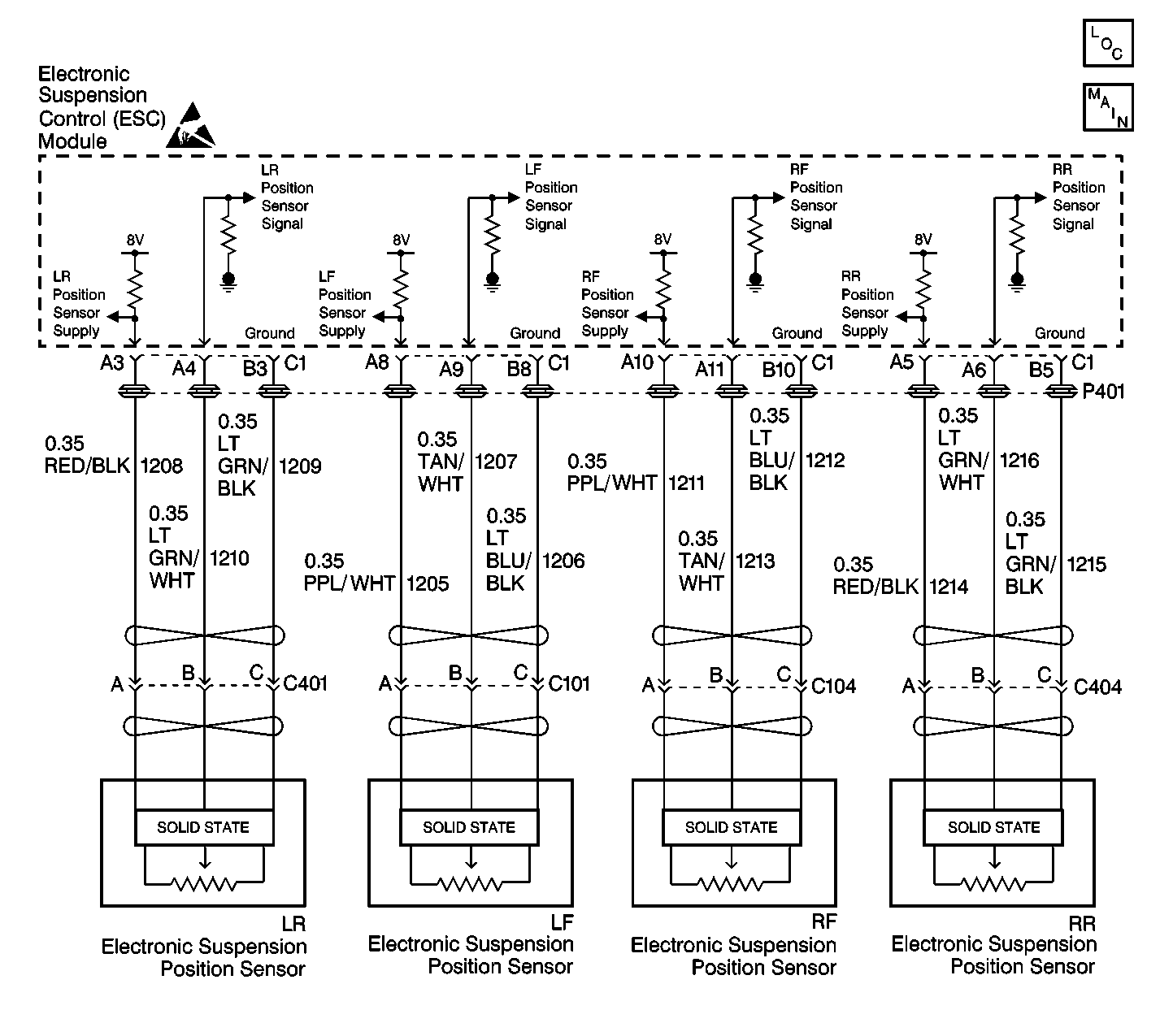
Circuit Description
The ESC module provides a common regulated power supply of about 8 volts to all of the position sensors. The ESC module monitors this power supply for a malfunction that could prevent it from correctly regulating the supply voltage.
Conditions for Setting the DTC
| • | The ESC module senses position sensor supply voltage under 6 volts or over 9 volts. |
| • | The condition must be detected for 1 second in 4 consecutive ignition cycles. |
Action Taken When the DTC Sets
| • | Stores a DTC C1768 in the ESC memory. |
| • | Provides shock absorber solenoid control based only on the vehicle speed. |
| • | Sends a message to the IPC to display the SERVICE RIDE CONTROL message. |
Conditions for Clearing the DTC
| • | A history DTC will clear after 100 consecutive ignition cycles if the condition for the malfunction is no longer present. |
| • | The ESC module senses the correct sensor supply voltage (6-9 volts). |
| • | The IPC clearing DTCs feature |
| • | Using a scan tool |
Diagnostic Aids
| • | The following conditions may cause an intermittent malfunction to occur: |
| - | An intermittent short to ground is detected on any of the position sensor supply circuits. |
| - | An intermittent short to voltage is detected on any of the position sensor supply circuits. |
| • | The ESC module uses a common power supply in order to provide voltage to all of the position sensors. Therefore, a position sensor (overcurrent) code may be set if a malfunction is detected on any position sensor supply circuit. |
| • | The ESC module uses an ignition cycle counter diagnostic approach to set this DTC. This requires the ESC module to detect the malfunction 4 times before setting the DTC. To disable this feature, use a scan tool to clear all DTCs before preforming diagnostic procedures. |
| • | If any position sensor supply circuit is shorted to ground, the scan tool will indicate all of the position sensor voltage readings as zero. |
| • | If any position sensor is shorted to voltage, the position sensor will still function properly and the scan tool will display a valid position sensor voltage reading. |
| • | An intermittent DTC C1768 may produce a random firm/soft condition. |
Test Description
The numbers below refer to the step numbers on the diagnostic table:
-
This step determines whether the malfunction is located in the position sensor supply circuit or in the position sensor itself.
-
This step uses a scan tool in order to determine whether a short to ground or a short to voltage is present in the position sensor supply circuit. A short to ground exists if the scan tool displays all position sensor voltage as zero.
-
This step determines what position sensor is causing the malfunction.
-
This step checks for an intermittent malfunction and requests a thorough inspection of all related position sensor supply circuit wiring and connectors.
Step | Action | Value(s) | Yes | No |
|---|---|---|---|---|
1 | Was the RTD Diagnostic System Check performed? | -- | ||
Is DTC C1768 current? | -- | |||
Are any of the position sensor voltage readings indicated under the specified value? | 1.0 V | |||
4 |
Was a circuit problem found and corrected? | -- | ||
5 |
Was a circuit problem found and corrected? | -- | ||
Does DTC C1768 set after reconnecting any position sensor? | -- | |||
Check all four position sensor supply circuits for an intermittent malfunction. Refer to Diagnostic Aids. Was an intermittent malfunction found and repaired? | -- | System OK | ||
8 | Replace the position sensor that indicated a malfunction when reconnected. Is the repair complete? | -- | -- | |
9 | Replace the ESC module. Refer to Electronic Suspension Control Module Replacement . Is the repair complete? | -- | -- | |
10 |
Is the repair complete? | -- | -- |
