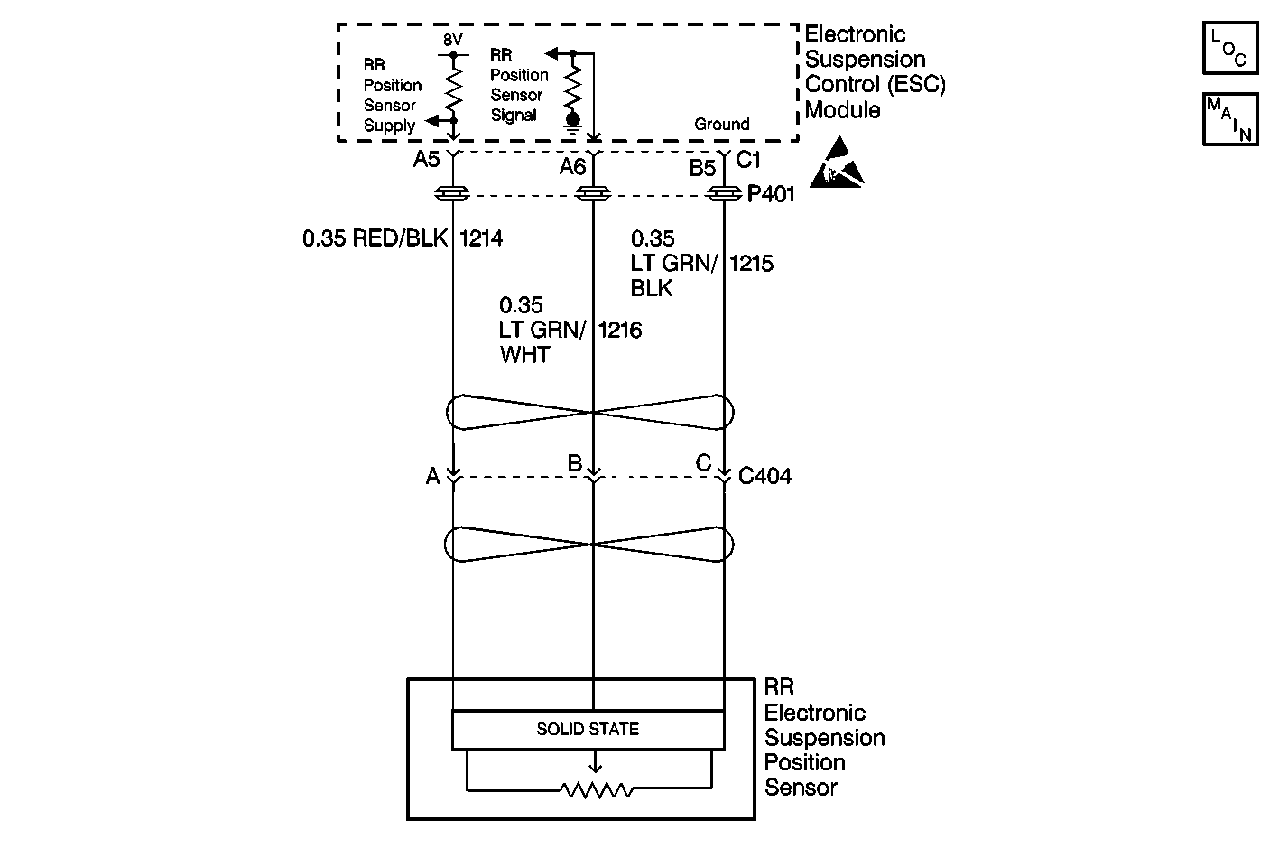
Circuit Description
The ESC module supplies 8 volts to the position sensors. The position sensors use the supplied 8 volts to produce an analog output range of 0-5 volts. The ESC module monitors the position sensor output voltage for an out of range condition. The position sensor normal operating range is 0.35-4.75 volts. An out of range condition is current if the data is not within this range.
Conditions for Setting the DTC
| • | The ESC module senses position sensor output voltage under 0.35 volts or over 4.75 volts. |
| • | The condition must be detected for 1 second in 4 consecutive ignition cycles. |
Action Taken When the DTC Sets
| • | Stores a DTC C1763 in the ESC memory. |
| • | Provides shocks absorber solenoid control based on the vehicle speed only. |
| • | Sends a message to the IPC to display the SERVICE RIDE CONTROL message. |
Conditions for Clearing the DTC
| • | A history DTC will clear after 100 consecutive ignition cycles if the condition for the malfunction is no longer present. |
| • | The ESC module senses the correct position sensor output voltage (0.35-4.75 volts) for 1 second. |
| • | Use the IPC clearing DTC feature. |
| • | Using a scan tool. |
Diagnostic Aids
| • | The following conditions may cause an intermittent malfunction to occur: |
| - | An intermittent open or short in the RR position sensor circuit. |
| - | Bent, disconnected, or damaged position sensor linkage. |
| • | When using a scan tool in order to read position sensor voltage, always make sure the vehicle is sitting with the full vehicle weight on its wheels. Measuring position sensor voltage with the vehicle raised and the wheels hanging may lead to incorrect diagnosis. |
| • | The ESC module uses an ignition cycle counter diagnostic approach to set this DTC. This requires the ESC module to detect the malfunction 4 times before setting the DTC. To disable this feature, use a scan tool to clear all DTCs before preforming diagnostic procedures. |
| • | The malfunction may be set due to a DTC C1768 Position Sensor Supply Overcurrent. If this is the case, go to DTC C1768 before proceeding with DTC C1763. |
| • | An intermittent DTC C1763 may produce a random firm/soft ride condition. |
| • | If the DTC is a history DTC, the problem may be intermittent. Using a scan tool, monitor the position sensor voltage while moving the wiring and the connectors. This can often cause the malfunction to occur. |
Test Description
The numbers below refer to the step numbers on the diagnostic table:
-
This step checks for a DTC C1768. This DTC must be diagnosed first before continuing to diagnose a DTC C1763.
-
This step measures the RR position sensor voltage with a scan tool and checks if the voltage readings are within a specified range.
-
This step checks for any visual damage to the RR position sensor.
-
This step checks if the ESC module is able to provide supply voltage to the RR position sensor.
-
This step checks if the ESC module is able to detect a change in position sensor voltage. The voltage reading will change from 0 volts (jumper removed) to 7.0-8.5 volts (jumper applied).
-
This step checks for an intermittent malfunction and requests a thorough inspection of the related RR position sensor circuit wiring and connectors.
Step | Action | Value(s) | Yes | No |
|---|---|---|---|---|
1 | Was the RTD Diagnostic System Check performed? | -- | ||
Using a scan tool, check if DTC C1768 is stored. Is DTC C1768 stored? | -- | Go to DTC C1768 Table | ||
Is the voltage indicated within the specified value? | 0.35-4.75 V | |||
Visually inspect the RR position sensor for signs of damage such as a bent arm or bracket, a disconnected sensor link, etc. Was the damage found and repaired? | -- | |||
Is the voltage indicated within the specified value? | 7.0-8.5 V | |||
Did the voltage reading on the scan tool change to the specified value with the jumper applied? | 4.0-5.5 V | |||
Check the RR position sensor circuit for an intermittent malfunction. Refer to Diagnostic Aids. Was an intermittent malfunction found and repaired? | -- | System OK | ||
8 | Check for an open, or a short to voltage on CKT 1215. Was a circuit problem found and repaired? | -- | ||
9 | Check for a short to ground, an open, or a short to voltage on CKT 1216. Was a circuit problem found and repaired? | -- | ||
10 | Check for an open, or short to voltage on CKT 1214. Was a circuit problem found and repaired? | - | ||
11 | Replace the RR position sensor. Refer to Electronic Suspension Rear Position Sensor Replacement . Is the repair complete? | -- | -- | |
12 | Replace the ESC module. Refer to Electronic Suspension Control Module Replacement . Is the repair complete? | -- | -- | |
13 |
Is the repair complete? | -- | -- |
