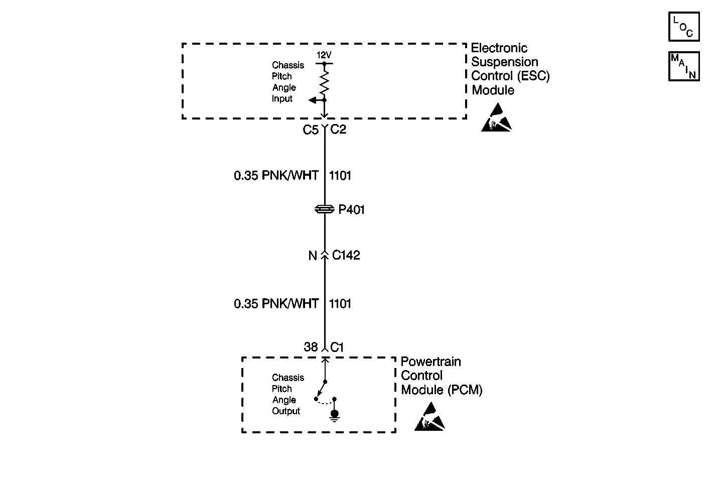
Circuit Description
The ESC module receives a chassis input from the PCM on CKT 1101. Under normal conditions, this signal is battery voltage. The PCM then grounds this circuit when the vehicle is accelerating rapidly or braking hard. When the chassis pitch input circuit goes low (about 0 volts), the ESC module commands all four shock absorber solenoids to a firm position. The PCM calculates the chassis pitch information based on the engine torque and the vehicle braking force. Once the ignition switch is turned to RUN, the ESC module sends a chassis pitch request to the PCM on the serial data line. The PCM then grounds the chassis pitch input circuit (pulling the circuit low for 5 seconds) and returns to normal operation.
Conditions for Setting the DTC
| • | After the ignition is turned to RUN, the ESC module does not detect a low to high transition on the chassis pitch input circuit from the PCM. |
| • | The ESC module will continue to send a request every 4 minutes to the PCM in order to retest for a chassis pitch circuit malfunction. |
| • | The condition must be detected within 31 seconds. |
Action Taken When the DTC Sets
| • | Stores a DTC C1744 in the ESC memory. |
| • | Ignores the chassis pitch input. |
| • | Sends a message to the IPC to display the SERVICE RIDE CONTROL message. |
Conditions for Clearing the DTC
| • | After the ignition is cycled, or after 4 minutes, the ESC module detects a low to high transition on the chassis pitch input circuit from the PCM within 31 seconds. |
| • | A history DTC will clear after 100 consecutive ignition cycles if the condition for the malfunction is no longer present. |
| • | Use the IPC clearing DTC feature. |
| • | Using a scan tool. |
Diagnostic Aids
| • | The following conditions may cause an intermittent malfunction to occur: |
| - | An intermittent open or short on the chassis pitch input CKT 1101. |
| - | An intermittent open or short to ground on the serial data line. |
| • | An intermittent short to ground or open on the chassis pitch input circuit may cause a random firm/soft ride condition. |
| • | If the DTC is a history DTC, the problem may be intermittent. Using a scan tool, monitor the chassis pitch input while moving the wiring and the connectors. This can often cause the malfunction to appear. |
Test Description
The numbers below refer to the step numbers on the diagnostic table:
-
This step checks if the ESC module is detecting the chassis pitch input status as ACTIVE.
-
This step checks if the PCM is the cause of the ESC module to detect the chassis pitch input status as ACTIVE.
-
This step checks if the ESC module is able to change the chassis pitch input status.
-
This step determines if the PCM chassis pitch output is functioning properly.
-
This step checks for an intermittent malfunction and requests a thorough inspection of the related chassis pitch circuit wiring and connectors.
Step | Action | Value(s) | Yes | No |
|---|---|---|---|---|
1 | Was the RTD Diagnostic System Check performed? | -- | ||
Does the scan tool still display the chassis pitch status as ACTIVE? | -- | |||
Disconnect the PCM connector C1. Does the scan tool still display the chassis pitch status as ACTIVE? | -- | |||
Does the scan tool display the chassis pitch status as ACTIVE with the jumper applied? | -- | |||
5 | Check for a short to ground in CKT 1101. Was a circuit problem found and repaired? | -- | ||
6 | Check for an open in CKT 1101. Was a circuit problem found and repaired? | -- | ||
Check the PCM for proper operation. Refer to Powertrain On Board Diagnostic (OBD) System Check in Engine Controls. Is the repair complete? | -- | -- | ||
Check the chassis pitch circuit for an intermittent malfunction. Refer to Diagnostic Aids. Was an intermittent malfunction found and repaired? | -- | |||
9 | Replace the ESC module. Refer to Electronic Suspension Control Module Replacement . Is the repair complete? | -- | -- | |
10 |
Is the repair complete? | -- | -- |
