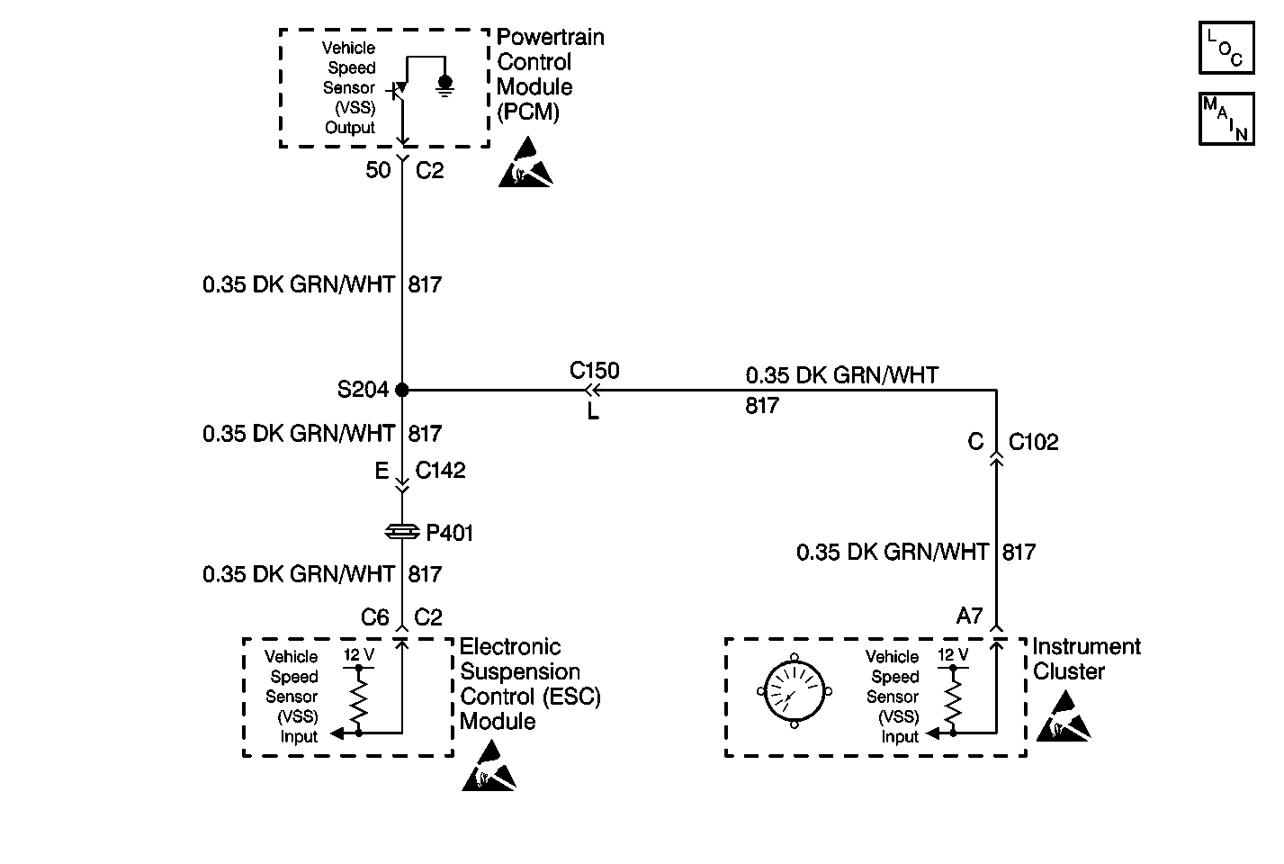
Circuit Description
The ESC module receives the vehicle speed signal from the PCM on CKT 817 and from the serial data line on CKT 1126. Once the vehicle speed has been detected, the ESC module compares the vehicle speed signal information received from the VSS (CKT 817 ) with the VSS data received on the serial data line (CKT 1126).
Conditions for Setting the DTC
| • | The ESC module receives VSS data from the PCM on the serial data line (CKT 1126) that is greater than 32 km/h (20 mph). |
| • | The ESC module receives VSS data from the PCM on CKT 817 that is less than 5 km/h (3 mph). |
| • | All conditions must be detected for 10 seconds. |
Action Taken When the DTC Sets
| • | Stores a DTC C1743 in the ESC memory. |
| • | Will use only the vehicle speed data obtained on the serial data line. |
Conditions for Clearing the DTC
| • | The ESC module receives VSS data (CKT 817) from the PCM greater than 5 km/h (3 mph). |
| • | A history DTC will clear after 100 consecutive ignition cycles if the condition for the malfunction is no longer present. |
| • | Use the IPC clearing DTC feature. |
| • | Using a scan tool. |
Diagnostic Aids
| • | The following conditions may cause an intermittent malfunction to occur: |
| - | An intermittent open or short (to ground or to voltage) on CKT 817. |
| - | An intermittent loss of VSS input to the PCM. |
| • | If the ESC module loses one of the two VSS inputs, the system will still function properly using the VSS data obtained from the input still functioning. The scan tool will display VSS data from the input still functioning. |
| • | Using a scan tool, check the PCM for VSS DTCs. If the PCM has any VSS PCMs stored in memory, refer to Engine Controls first before attempting any further diagnostic procedures on the RTD system. |
Test Description
The numbers below refer to the step numbers on the diagnostic table:
-
This step checks if the speedometer is receiving a VSS signal from the PCM.
-
This step checks if the ESC module is the cause of the VSS circuit malfunction.
-
This step checks for an intermittent malfunction and requests a thorough inspection of the related VSS circuit wiring and connectors.
Step | Action | Value(s) | Yes | No |
|---|---|---|---|---|
1 | Was the RTD Diagnostic System Check performed? | -- | ||
Using a scan tool, select the PCM DTC display. Are any PCM VSS DTCs stored? | -- | |||
Test drive the vehicle while checking the speedometer operation. Does the speedometer operate correctly? | -- | |||
4 |
Does the speedometer operate correctly? | -- | ||
Check for an open in CKT 817 between S204 and the ESC module connector terminal C6. Was a problem found and repaired? | -- | |||
6 | Check the VSS circuit for an intermittent malfunction. Refer to Diagnostic Aids. Was an intermittent malfunction found and repaired? | -- | ||
7 |
Does DTC C1743 reset? | -- | System OK | |
8 | Replace the ESC module. Refer to Electronic Suspension Control Module Replacement . Is the repair complete? | -- | -- | |
9 |
Is the repair complete? | -- | -- |
