The charging system consists of the following components:
| • | The battery |
| • | The generator (CS-130D) |
| • | A voltage regulator |
| • | Indicator lamp or voltmeter circuitry |
CS-Series Generators

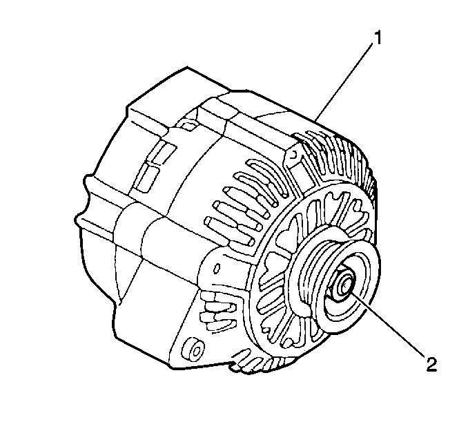
Model CS-Series generators (1) feature a high ampere output per pound of weight. The CS stands for charging systems. The 130 is the measurement, in millimeters, of the outside diameter of the stator laminations and the D is for dual internal fans. The delta stator, rectifier bridge, and the rotor with slip rings and brushes, are electrically similar to other CS series generators. The CS-130D generator uses a conventional pulley and dual internal fans to cool the slip ring end frame, rectifier bridge and voltage regulator.
The generator's rotor shaft (2) is rotated by the engine drive belt. The rotor shaft rotates the generator's rotor. The generator produces the electrical current that charges the battery. The generator also provides energy to the vehicle's electrical systems when the engine is running.
Charging System Operation

The charging system provides voltage to the battery and to the vehicle electrical systems. The generator's voltage regulator controls the rotor's field current to meet these needs.
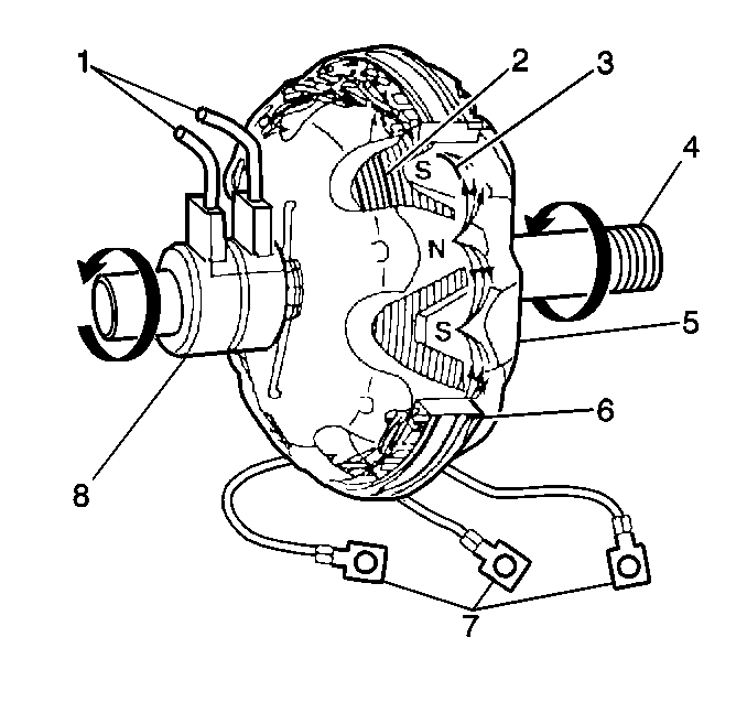
Current flows (1) through the slip rings (8) to the rotor winding (2) in order to create a magnetic field (3). The engine-driven rotor (4) is rotated by the engine within the stator (5). This rotation creates an alternating current (AC) voltage in the stator windings (6). The AC voltage goes to the rectifier bridge (7). The rectifier bridge converts this AC voltage to direct current (DC) voltage. The DC voltage is delivered from the generator's output terminal to the battery and the electrical systems through a fusible link (11). The regulator grounds circuit 225 (10) when the charging system voltage is abnormal. This information causes the PCM to send a class 2 message to the instrument panel cluster, which activates the CHECK GAGES lamp.
The voltage regulator limits system voltage by controlling the rotor field current. When the field ccurrent is on, the regulator switches the rotor field on and off at a fixed rate of about 400 cycles per second. By varying the overall on/off time, correct average field current for proper system voltage control is maintained. At high speeds, the on time may be 10 percent and the off time may be 90 percent. At low speeds, and with high electrical loads, the on/off time may be 90 percent and 10 percent respectively. The voltmeter reads battery voltage when the engine is not running and reads charging system voltage when the engine is running. The normal indication is between 11 and 16 volts.
The generator uses only two connections-battery positive and the L terminal, in addition to the ground path through the generator bracket. Use of P, I, and S terminals is optional. The P terminal is connected to the stator and may be connected externally to a tachometer or other devise. The I terminal can be connected directly to battery voltage to power the generator instead of, or in addition to, the L terminal which must be stepped down. This S terminal may be connected to an external voltage source, such as voltage near the battery, for voltage control. If the S terminal is not used, internal generator voltage is used for control.
The CS-130D generator must be replaced. Do not disassemble the CS-130D generator.
