Important:
• Do not substitute a PCM from another vehicle for diagnosis. The PCM will
not recognize the Vehicle Theft Deterrent password from the BCM. The PCM
disables the fuel, and the PCM stores DTC P1631 into history. • The following must be performed anytime the PCM is replaced: - Program the PCM - The PCM Password Learn procedure - The Idle Learn Procedure - The Oil Life reset procedure - The Functional Check • The following must be performed anytime the PCM is disconnected, loses
power or is reprogrammed: - The Idle Learn Procedure - The Functional Check
Removal Procedure
Important: Remove any debris from the PCM connector surfaces before servicing the PCM. Inspect the PCM module connector gaskets when diagnosing/replacing the PCM. Ensure that the gaskets are installed correctly. The gaskets prevent contaminate intrusion into the PCM.
Notice: Do not touch the connector pins or soldered components on the circuit board in order to prevent possible electrostatic discharge (ESD) damage to the PCM.
Important: The ignition should always be OFF when installing or removing the PCM/TAC module connectors.
- Using a scan tool, retrieve the percentage of remaining engine oil. Record the remaining engine oil life.
- Raise the vehicle. Refer to Lifting and Jacking the Vehicle in General Information.
- Remove the right front tire and wheel assembly. Refer to Tire and Wheel Removal and Installation in Tires and Wheels.
- Remove the wheelhouse filler panel. Refer to Wheelhouse Filler Replacement in Body Front End.
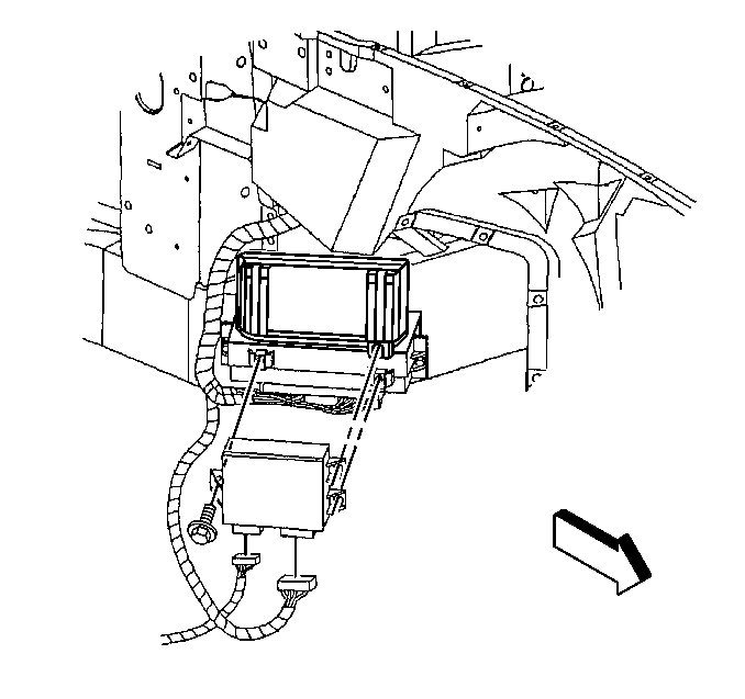
- Remove the fasteners retaining the Throttle Actuator Control (TAC) module to the PCM mounting bracket.
- Remove the electrical connectors from the TAC module.
- Remove the TAC module from the vehicle.
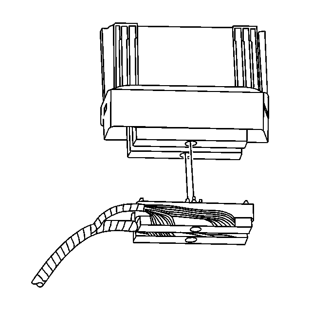
- Disconnect the PCM electrical harness connectors.
- Loosen but do not remove the PCM rear retaining fastener. Use the rear retaining fastener as an anchor for the outer bracket.
- Remove the front retaining fastener from the PCM.
- Reposition the PCM outer bracket.
- Remove the PCM from the bracket and the vehicle.
Important: It is necessary to record the remaining engine oil life. If the replacement module is not programed with the remaining engine oil life, the engine oil life will default to 100%. If the replacement module is not programmed with the remaining engine oil life, the engine oil will need to be changed at 5000 km (3,000 mi) from the last engine oil change.


Important:: The remaining steps are for the PCM replacement.
Installation Procedure
- Install the PCM to the PCM rear bracket.
- Position the PCM front bracket.
- Install the PCM front retaining fasteners.
- Connect the electrical connectors to the PCM.
- Connect the electrical connectors to the TAC module.
- Align the hole in the rear mounting tab of the TAC module to the corresponding hole in the PCM mounting bracket. Position the TAC module below the rear mounting tab for greater clearance in order to install the rear retaining fastener.
- Install the TAC module rear retaining fastener.
- Align the front mounting holes of the TAC module.
- Install the TAC module front retaining fasteners.
- Install the wheelhouse filler panel. Refer to Wheelhouse Filler Replacement in Body Front End.
- Install the right front tire and wheel assembly. Refer to Tire and Wheel Removal and Installation in Tires and Wheels.
- Lower the vehicle.
- Program the PCM if a new PCM is being installed.

Notice: Use the correct fastener in the correct location. Replacement fasteners must be the correct part number for that application. Fasteners requiring replacement or fasteners requiring the use of thread locking compound or sealant are identified in the service procedure. Do not use paints, lubricants, or corrosion inhibitors on fasteners or fastener joint surfaces unless specified. These coatings affect fastener torque and joint clamping force and may damage the fastener. Use the correct tightening sequence and specifications when installing fasteners in order to avoid damage to parts and systems.
Tighten
Tighten the PCM retaining fasteners to 2.2 N·m
(17 lb in).

Tighten
Tighten the PCM electrical connectors to 8 N·m
(70 lb in).

Tighten
Tighten the TAC module retaining fasteners to 1.9 N·m
(17 lb in).

PCM Programming
Setup
- Ensure that the following conditions have been met:
- Turn OFF the ignition.
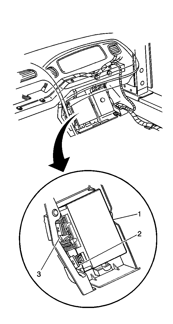
- Remove the passenger side (right side of vehicle) floor access panel. Refer to Kick-Up Panel Replacement - Front Floor in Interior Trim.
- Remove the splice pack/star connector shorting bars from both splice pack/star connectors (2 and 3). It may be necessary to remove splice pack/star connectors from the mounting positions.
- Install the Star Connector cable #1 from the J 42236 to the 12 pin splice pack/star (3). This is the connector with 8 or 9 wires.
- Install the Star Connector cable #2 from the J 42236 to the 12 pin splice pack/star (2). This is the connector with 4 wires.
- Select the Star Connector cable #1 on the J 42236 toggle switch.
- Select position B on the J 42236 .
- Turn ON the ignition leaving the engine OFF.
- Program the PCM using the latest software matching the vehicle. Refer to the Techline terminal/equipment users instructions.
- Perform the PCM Password Learn procedure if a new PCM is installed. Refer to DTC P1631 Theft Deterrent Start Enable Signal Not Correct for learn procedure.
- Perform the PCM Idle Learn procedure. Refer to Idle Learn .
- Perform the Oil Life Reset procedure if a new PCM is installed.
| • | The battery is fully charged. |
| • | The scan tool cable connection at the DLC is secure. |

| • | If the PCM fails to program, proceed as follows: |
| - | Ensure that all PCM connections are OK. |
| - | Ensure that all connections at the splice pack/star connectors are OK. |
| - | Verify the Techline terminal/equipment for the latest software version. |
| - | Attempt to program the PCM. Replace the PCM if the PCM still cannot be programmed properly. |
| • | Program the replacement PCM. |
Functional Check
- Clear the Diagnostic Trouble Codes (DTCs).
- Perform the On-Board Diagnostic System Check.
- Start the engine and run for 1 minute.
- Scan for DTCs using the scan tool.
