Removal Procedure
Tools Required
| • | J 33432-A Transverse Leaf Spring Compressor |
| • | J 42188 Ball Joint Separator |
| • | J 41803 Engine Support Fixture |
| • | J 28467-B Universal Engine Support Fixture |
- Disconnect the negative battery cable.
- Remove the front crossmember. Refer to Front Suspension Crossmember Replacement in Front Suspension.
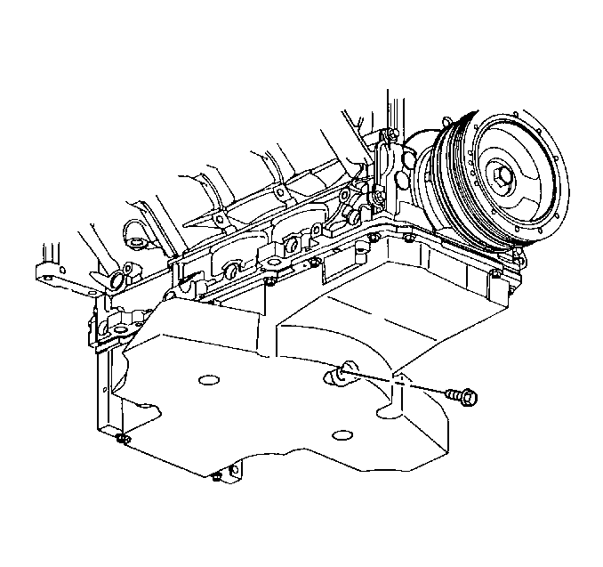
- Remove the oil drain plug.
- Drain the oil from the engine.
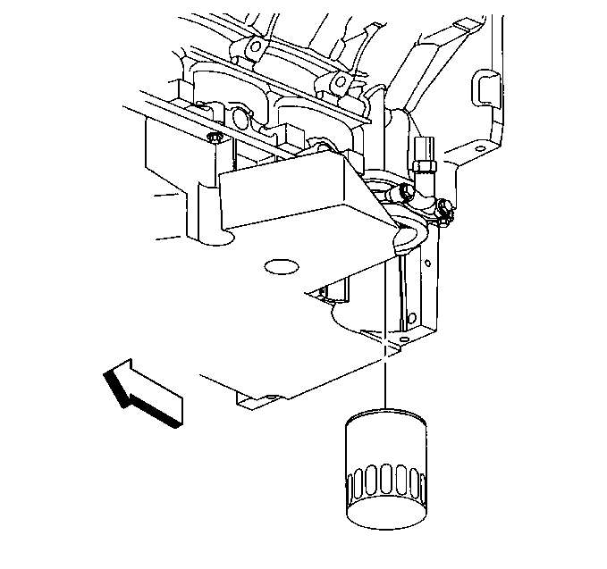
- Remove the oil filter from the oil pan.
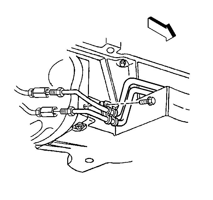
- Remove the automatic transmission cooler line front and rear retaining clamp bolts (if equipped).
- Remove the engine flywheel housing-to-oil pan bolts.
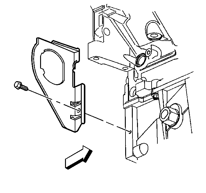
- Remove the engine flywheel housing closeout bolts.
- Disconnect the electrical connector and remove the engine oil level sensor.
- Disconnect the engine oil temperature sensor electrical connector.
- Remove the oil pan bolts.
- Remove the oil pan.
- Drill (3) out the oil pan retaining rivets (2) (if required).
- Remove the oil pan gasket (1) from the oil pan.
- Discard the gasket and rivets.
Caution: Unless directed otherwise, the ignition and start switch must be in the OFF or LOCK position, and all electrical loads must be OFF before servicing any electrical component. Disconnect the negative battery cable to prevent an electrical spark should a tool or equipment come in contact with an exposed electrical terminal. Failure to follow these precautions may result in personal injury and/or damage to the vehicle or its components.
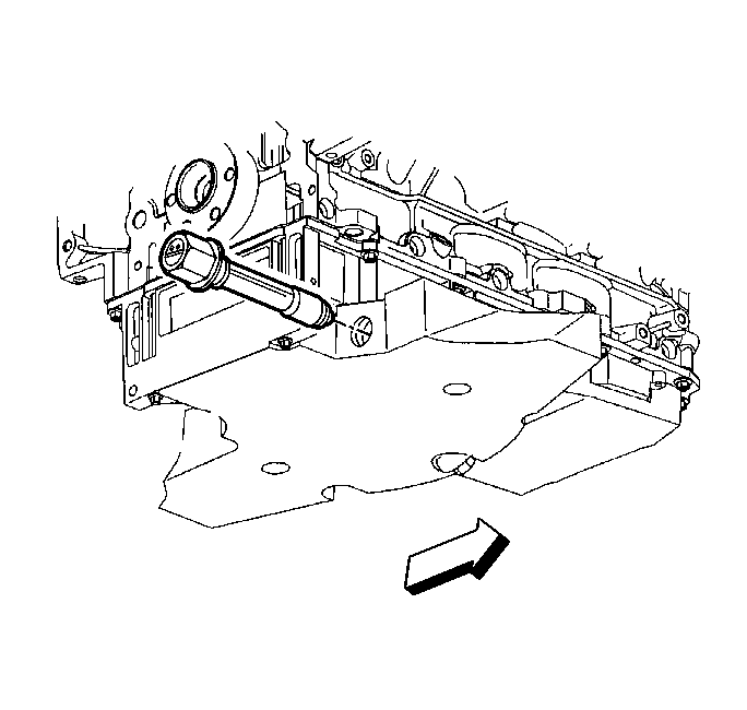
Important: The original oil pan gasket is retained and aligned to the oil pan by rivets. When installing a new gasket, it is not necessary to install new oil pan gasket rivets.
DO NOT reuse the oil pan gasket. When installing the oil pan, install a NEW oil pan gasket.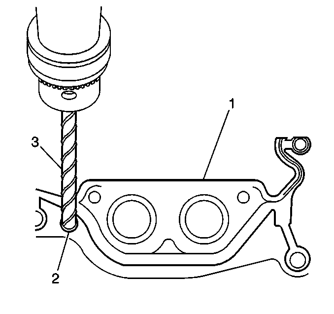
Important: DO NOT allow foreign material to enter the oil passages of the oil pan, cap or cover the openings as required.
Use care not to gouge, score, or damage the oil pan sealing surface.Installation Procedure
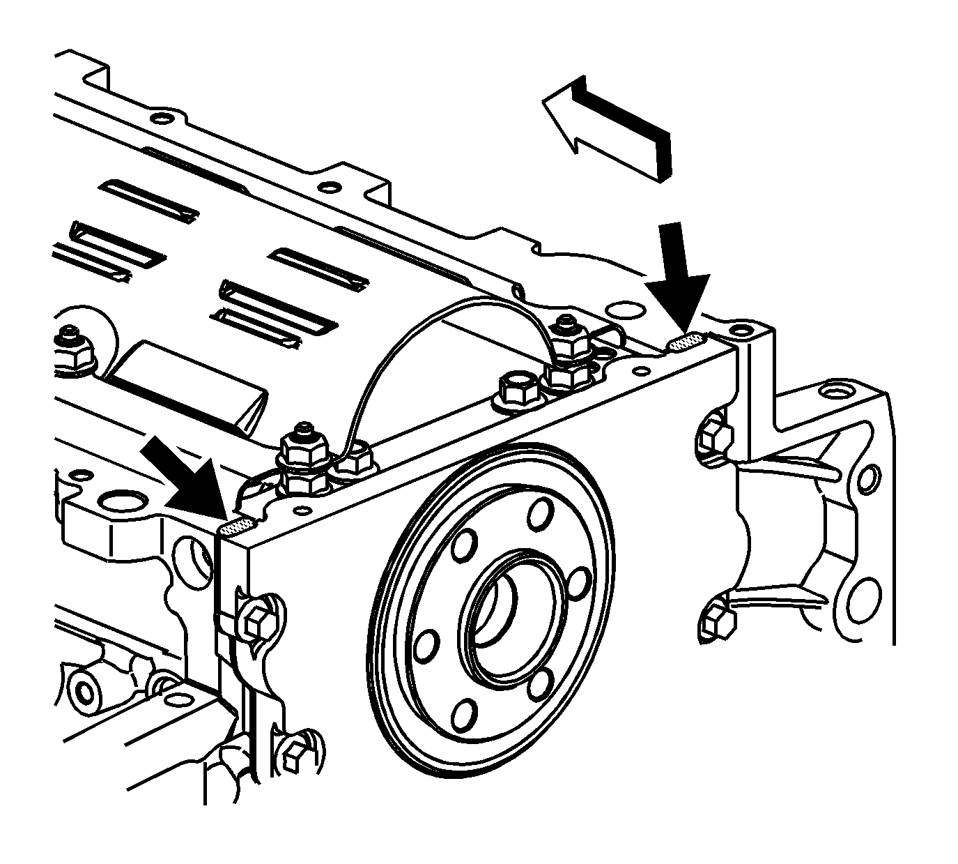
- Apply a 5 mm (0.20 in) bead of sealant GM P/N 12378190 or equivalent 20 mm (0.80 in) long to the engine block. Apply the sealant directly onto the tabs of the front cover gasket that protrude into the oil pan surface.
- Apply a 5 mm (0.20 in) bead of sealant GM P/N 12378190 or equivalent, 20 mm (0.80 in) long to the engine block. Apply the sealant directly onto the tabs of the rear cover gasket that protrude into the oil pan surface.
- Preassemble the oil pan gasket to the pan.
- Install the oil pan, gasket and bolts to the engine block.
- Tighten the oil pan bolts finger tight. Do not overtighten.
- Install the two lower flywheel housing bolts to position the oil pan correctly.
- Tighten the lower flywheel housing bolts finger tight. Do not overtighten.
- Tighten the oil pan-to-block and oil pan-to-oil pan front cover bolts to 25 N·m (18 lb ft).
- Tighten the oil pan-to-rear cover bolts to 12 N·m (106 lb in).
- Tighten the flywheel housing bolts to 50 N·m (37 lb ft).
- Install the left side closeout and bolt.
- Install the right side closeout and bolt.
- Connect the engine oil temperature sensor connector.
- Install and connect the engine oil level sensor.
- Install the automatic transmission cooler pipe front retaining clamp bolt.
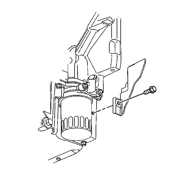
- Install the automatic transmission cooler pipe rear retaining clamp bolt.
- Install the oil filter to the oil pan.
- Install the oil drain plug.
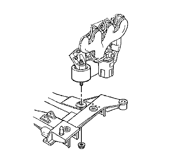
- Install the front crossmember to the vehicle. Refer to Front Suspension Crossmember Replacement in Front Suspension.
- Fill the engine with oil.
- Fill the transmission fluid.
- Connect the negative battery cable.
- Program the Transmitters. Refer to Transmitter Programming/Synchronization in Keyless Entry.
- Check for leaks.
- Align the front suspension as necessary. Refer to Wheel Alignment Measurement in Wheel Alignment.
Important: All gasket surfaces should be free of oil or other foreign material during assembly.
The alignment of the structural oil pan is critical. The rear bolt hole locations of the oil pan provide mounting points for the flywheel housing cover. To ensure the rigidity of the powertrain and correct transmission alignment, it is important that the rear of the block and the rear of the oil pan are flush or even. The rear of the oil pan must NEVER protrude beyond the engine block . Do NOT reuse the oil pan gasket. It is not necessary to rivet the NEW gasket to the oil pan.
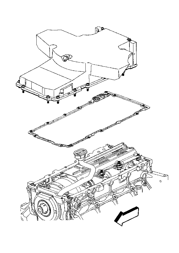
Important: Be sure to align the oil gallery passages in the oil pan and engine block properly with the oil pan gasket.
| 3.1. | Install the gasket onto the oil pan. |
| 3.2. | Install the oil pan bolts to the pan and through the gasket. |
Notice: Use the correct fastener in the correct location. Replacement fasteners must be the correct part number for that application. Fasteners requiring replacement or fasteners requiring the use of thread locking compound or sealant are identified in the service procedure. Do not use paints, lubricants, or corrosion inhibitors on fasteners or fastener joint surfaces unless specified. These coatings affect fastener torque and joint clamping force and may damage the fastener. Use the correct tightening sequence and specifications when installing fasteners in order to avoid damage to parts and systems.
Tighten
Tighten
Tighten the left side closeout bolt to 12 N·m (106 lb in).

Tighten
Tighten the right closeout cover bolt to 12 N·m (106 lb in).

Tighten
Tighten the oil level sensor to 13 N·m 115 lb in).
Tighten
Tighten the automatic transmission cooler pipe front retaining clamp
bolt to 12 N·m (106 lb in).
Tighten
Tighten the automatic transmission cooler pipe rear retaining clamp
bolt to 2.5 N·m (22 lb in).

Tighten
Tighten the oil filter to 30 N·m (22 lb ft).
Tighten
Tighten the oil drain plug to 25 N·m (18 lb ft).
Tighten
Tighten the negative battery cable bolt to 15 N·m (11 lb ft).
