Name | Location | Locator View | Connector End View | Group No. |
|---|---|---|---|---|
Battery | LH rear of the engine compartment, near the bulkhead | 8A-201-5 Fig. 12 | -- | -- |
Central Control Module (CCM) | Behind the center of the I/P, behind the radio control head | 8A-201-16 Fig. 31 | 8A-51-6 | 2.560 |
Clutch Pedal Position Switch (M/T) | Under the LH of the I/P, mounted to the top of the clutch pedal | 8A-201-19 Fig. 37 | 8A-202-27 | 4.054 |
Driver Information Center (DIC) | Center of the I/P | 8A-201-17 Fig. 32 | 8A-86-3 | 9.768 |
Fusible Link A | LH rear of the engine compartment, between the battery and the bulkhead | 8A-201-5 Fig. 12 | -- | -- |
Fusible Link B | LH rear of the engine compartment, between the battery and the bulkhead | 8A-201-5 Fig. 12 | -- | -- |
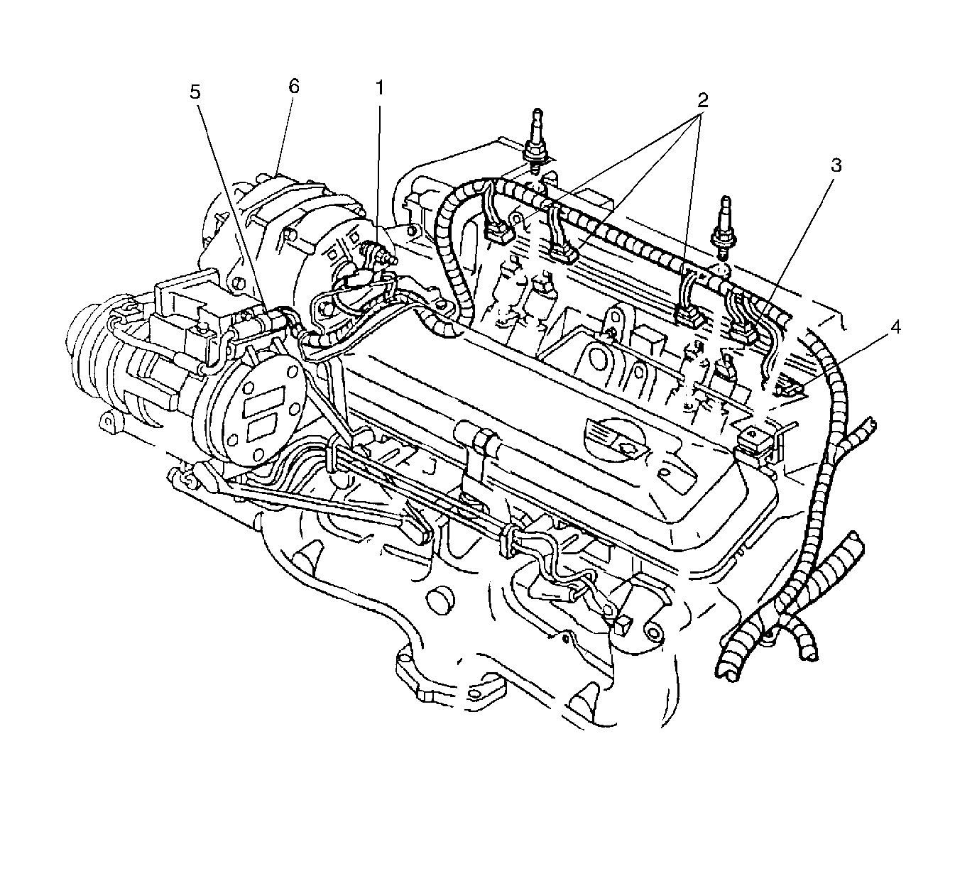
Generator | Top LH front of the engine |
| 8A-202-29 | 02.275 |
I/P Fuse Block | Far RH side of the I/P, visible with the door open | 8A-201-14 Fig. 25 | -- | -- |
Ignition Switch | Below LH side of the I/P, attached to the steering column | 8A-201-20 Fig. 38 | 8A-202-31 | 2.188 |
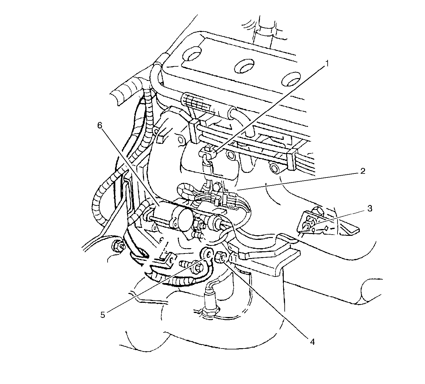
Starter Motor | Lower RH of the engine |
| -- | 02.041 |
Starter Solenoid | Lower RH of the engine | 8A-201-9 Fig. 17 | -- | -- |
Theft Deterrent Relay | Behind LH of the I/P, LH of the steering column | 8A-201-18 Fig. 34 | 8A-202-26 | 2.100 |
Transmission Range Switch (A/T) | In the center console, at the base of the gear selector lever | 8A-201-22 fig. 43 | 8A-202-34 | 4.054 |
Underhood Fuse Block #1 | LH rear of the engine compartment, behind the battery, attached to the bulkhead | 8A-201-5 Fig. 12 | -- | -- |
Underhood Fuse Block #2 | LH rear of the engine compartment, in front of the battery, attached inside of the wheelhouse | 8A-201-5 Fig. 12 | -- | -- |
C100A | The I/P harness to the engine/forward lamp harnesses, LH rear of the I/P, passing through to LH rear of the engine compartment at the bulkhead | 8A-201-19 Fig. 36 | 8A-202-13 | -- |
C100C | The engine harness to the I/P harness (C100A), LH rear of the engine compartment near the battery, attached to the bulkhead | 8A-201-5 Fig. 12 | 8A-202-13 | -- |
C239 | The I/P harness to the engine harness, RH rear of the I/P, near the I/P fuse block | 8A-201-14 Fig. 25 | 8A-202-19 | -- |
G101 | LH rear of the engne compartment, on the frame rail, below the battery | 8A-201-5 Fig. 12 | -- | -- |
G102 | LH rear of the engne compartment, on the frame rail, below the battery | 8A-201-5 Fig. 12 | -- | -- |
G106 | LH rear of the engine, near the oil filter | 8A-201-5 Fig. 12 | -- | -- |
G107 | LH rear of the engine, on the bell housing | 8A-201-7 Fig. 15 | -- | -- |
P101 | Rear and center of the engine compartment, in the bulkhead, the engine harness to the I/P compartment | 8A-201-3 fig. 8 | -- | -- |
S215 | The I/P harness, center rear of I/P in the DIC connector branch, approximately 6 cm from the base of the connector breakout | -- | -- | -- |
S227 | The I/P harness, center rear of the I/P, approximately 17 cm to the LH of the diagnostic energy reserve module (DERM) connector breakout | -- | -- | -- |
S233 | The I/P harness, LH rear of the I/P, approximately 6 cm to the LH of the I/P cluster connector breakout | -- | -- | -- |
S278 | The I/P harness, RH rear of the I/P, approximately 9.5 cm to the LH of the I/P fuse block breakout | -- | -- | -- |


